Content .. 1060 1061 1062 1063 ..
Mitsubishi Montero (2004+). Manual - part 1062
ANTI-LOCK BRAKING SYSTEM (ABS) DIAGNOSIS
TSB Revision
ANTI-LOCK BRAKING SYSTEM (ABS)
35B-91
Q: Are the harness wires between ignition switch (IG2)
connector D-204 terminal 4 and M-ASTC-ECU
connectors E-119 terminal 9 and E-120 terminal 63
damaged?
YES : Repair them and then go to Step 5.
NO : Go to Step 5.
AC204385
AC204673
CONNECTOR: E-111
AB
E-111
9
21
33
35
24
12
3 4
7
8
5 6
39
28
41
30
18
4243
31
1920
32
40
29
1617
38
27
15
37
36
26
14
13
25
2
1
34
23
11
10
22
E-111
AC204384
D-116
AE
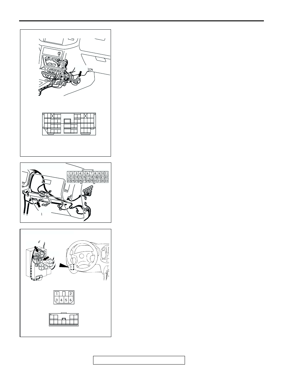
CONNECTOR: D-116
AC204624 AF
CONNECTORS: D-208, D-212
D-208
JUNCTION BLOCK
(FRONT VIEW)
JUNCTION BLOCK CONNECTOR
D-212
D-212
D-208
6
2
5
1
7 8
11
4
9 10
3
JUNCTION BLOCK CONNECTOR