Mitsubishi Montero (2004+). Manual - part 1058


  Index      Mitsubishi     Mitsubishi Montero - service repair manual 2004 year


Search            


Content   ..  1056  1057  1058  1059   ..


Mitsubishi Montero (2004+). Manual - part 1058


ANTI-LOCK BRAKING SYSTEM (ABS) DIAGNOSIS

TSB Revision

ANTI-LOCK BRAKING SYSTEM (ABS)

35B-75

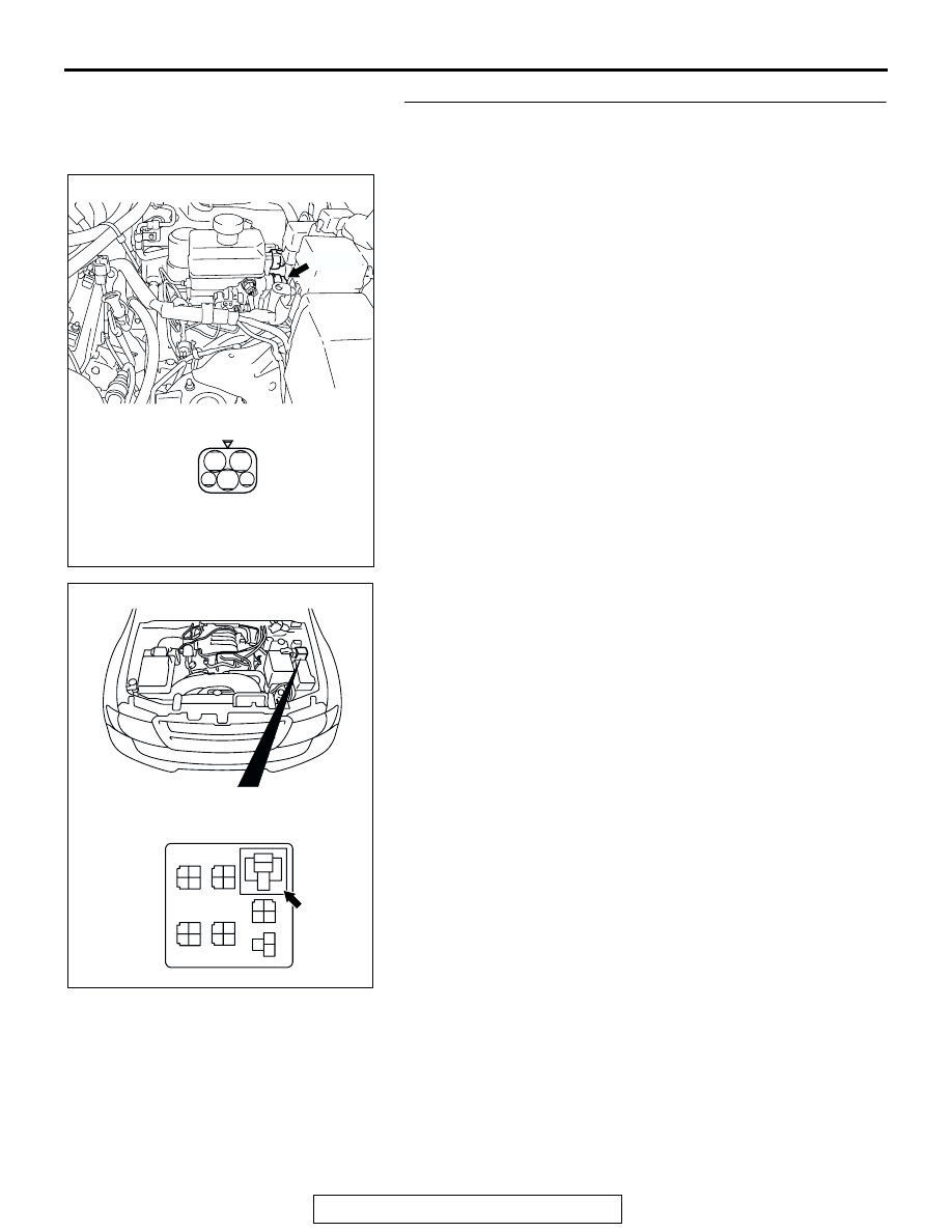
STEP 8. Check the harness wire between valve relay 
connector B-21X terminal 2 and HBB connector B-18 
terminal 34.
NOTE:  After inspecting HBB connector B-18, inspect the wire. 
If HBB connector B-18 is damaged, repair or replace it. Refer to 
GROUP 00E, Harness Connector Inspection 

P.00E-2

. If the 

connector has been repaired or replaced, go to Step 10.
Q: Is the harness wire between valve relay connector 

B-21X terminal 2 and HBB connector B-18 terminal 34 
damaged?
YES : 
Repair it and then go to Step 10.
NO :  Go to Step 9.

AC204626 AB

CONNECTOR: B-18

B-18 (B)

HARNESS CONNECTOR : 
COMPONENT SIDE

34

32

31

33

35

B-18

AC204706

1

2

3

4

1

2

3

4

1

2

3

4

1

2

3

4

1

2

3

4

1

2

3

4

1

2

3

5

B-21X

CONNECTOR: B-21X

AB

RELAY BOX CONNECTOR

ANTI-LOCK BRAKING SYSTEM (ABS) DIAGNOSIS

TSB Revision

ANTI-LOCK BRAKING SYSTEM (ABS)

35B-76

STEP 9. Check the HBB.
(1) Disconnect HBB connector B-17 and B-18, and measure at 

the HBB side.

(2) Check for continuity between HBB connector B-17 

terminals 3 and HBB connector B-18 terminal 34. It should 
be continuity (approximately 33

Ω). 

Q: Is there continuity between HBB connector B-17 

terminal 3 and HBB connector B-18 terminal 34?
YES : 
Replace the M-ASTC-ECU and then go to Step 10.
NO :  Replace the HBB master cylinder and hydraulic unit 

assembly. Then go to Step 10.

STEP 10. Recheck for diagnostic trouble code.
Q: Does DTC 52 reset?

YES : Go to Step 1.
NO :  The procedure is complete.

AC205740AB

CONNECTORS: B-17, B-18

B-17 (GR)

B-18 (B)

B-17

B-18

HBB CONNECTORS

HBB CONNECTORS

ANTI-LOCK BRAKING SYSTEM (ABS) DIAGNOSIS

TSB Revision

ANTI-LOCK BRAKING SYSTEM (ABS)

35B-77

DTC 61 : Master Cylinder Pressure Sensor System

.

CIRCUIT OPERATION
The master cylinder pressure sensor is monitoring 
the brake fluid pressure to the rear wheels. The mas-
ter cylinder pressure sensor sends a signal from its 
terminal No.1, and the M-ASTC-ECU receives the 
signal at its connector No.59.

.

ABS DTC SET CONDITIONS
DTC 61 is set in the following case.

• When the power supply voltage is abnormally 

high or low

• When the master cylinder pressure sensor output 

signal is abnormally high or low

.

TROUBLESHOOTING HINTS

• Damaged wiring harness or connector

• Malfunction of the master cylinder pressure sen-

sor

• Malfunction of the M-ASTC-ECU

.

DIAGNOSIS

Required Special Tools:

•  MB991958: Scan Tool (MUT-III Sub Assembly)

• MB991824: Vehicle Communication Interface (V.C.I.)

• MB991827: MUT-III USB Cable

• MB991911: MUT-III Main Harness B

Master Cylinder Pressure Sensor Circuit

AC204772AB

B-55(GR)

CONNECTOR: B-55

AC203901AF

CONNECTOR: E-120

E-120

ANTI-LOCK BRAKING SYSTEM (ABS) DIAGNOSIS

TSB Revision

ANTI-LOCK BRAKING SYSTEM (ABS)

35B-78

• MB991223: Harness Set 

STEP 1. Check the power supply circuit at pressure sensor 
connector B-55.
(1) Do not disconnect pressure sensor connector B-55.
(2) Turn the ignition switch to the "ON" position.
(3) Measure voltage between terminal 2 and ground. It should 

be approximately 5 volts.

Q: Is the voltage approximately 5 volts?

YES : Go to Step 4.
NO :  Go to Step 2.

AC204772

AC204773AB

B-55(GR)

CONNECTOR: B-55

1

3

2

HARNESS CONNECTOR:
COMPONENT SIDE


Content   ..  1056  1057  1058  1059   ..