Content .. 1003 1004 1005 1006 ..
Mitsubishi Montero (2004+). Manual - part 1005
HYDRAULIC BRAKE BOOSTER (HBB) DIAGNOSIS
TSB Revision
BASIC BRAKE SYSTEM
35A-19
.
CIRCUIT OPERATION
The M-ASTC-ECU has two power supply lines. An
M-ASTC-ECU power is supplied to the
M-ASTC-ECU (terminal 9) from the ignition switch
(IG2) through the multi-purpose fuse number 17 in
the junction block. The other M-ASTC-ECU power is
supplied to the M-ASTC-ECU (terminal 63) from the
ignition switch (IG2) through the multi-purpose fuse
number 5 in the junction block and through the joint
connector number 4.
.
HBB DTC SET CONDITIONS
DTC16 is set if the voltage at both of the power line is
extremely low or high.
.
TROUBLESHOOTING HINTS
• Malfunction of the battery
• Malfunction of the charging system
• Malfunction of the M-ASTC-ECU
.
DIAGNOSIS
Required Special Tools:
• MB991958: Scan Tool (MUT-III Sub Assembly)
• MB991824: Vehicle Communication Interface
(V.C.I.)
• MB991827: MUT-III USB Cable
• MB991911: MUT-III Main Harness B
STEP 1. Check the battery.
Refer to GROUP 54A, Battery
− On-vehicle Service
− Battery Testing Procedure
Q: Is the battery damaged?
YES :
Charge or replace the battery and then go
to Step 4.
NO :
Go to Step 2.
STEP 2. Check the charging system.
Refer to GROUP 16, Charging System
− Diagnosis
Q: Is the charging system damaged?
YES :
Repair the Charging System and then go to
Step 4.
NO :
Go to Step 3.
STEP 3. Recheck for diagnostic trouble code.
(1) Erase the DTC memory.
(2) Recheck for diagnostic trouble code.
Q: Is DTC 16 set?
YES :
Replace the M-ASTC-ECU (Refer to
GROUP 35C, M-ASTC-ECU
Then go to Step 4.
NO :
It can be assumed that this malfunction is
intermittent. Refer to GROUP 00, How to
Use Troubleshooting/Inspection Service
Points
− How to Cope with Intermittent
Malfunction
.
STEP 4. Recheck for diagnostic trouble code.
(1) Erase the DTC memory.
(2) Recheck for diagnostic trouble code.
Q: Is DTC 16 set?
YES :
Start over at Step 1.
NO :
The procedure is complete.
AC204548 AB
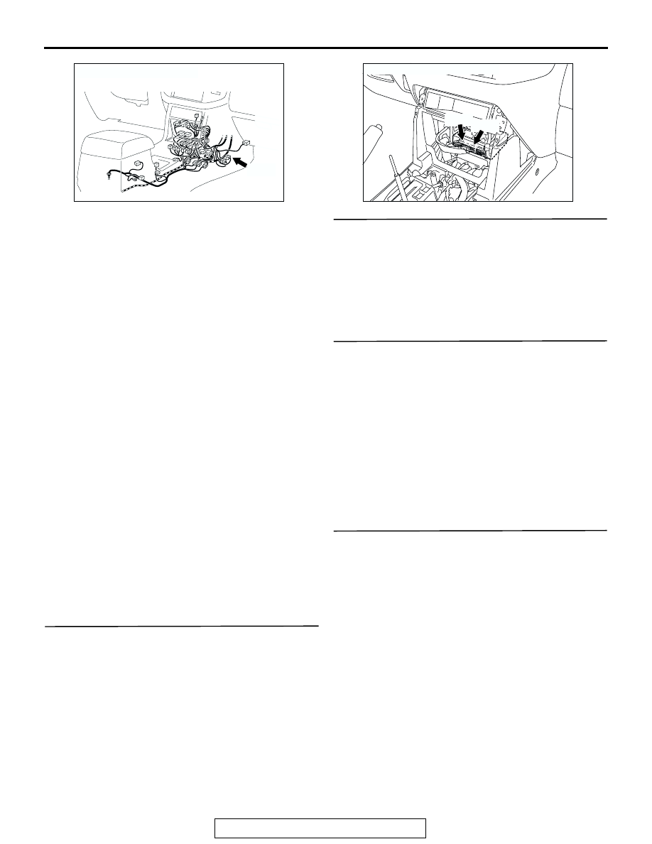
CONNECTOR: E-111
E-111
AC203901AD
CONNECTORS: E-119, E-120
E-119
E-120