Mitsubishi Montero (2004+). Manual - part 7


  Index      Mitsubishi     Mitsubishi Montero - service repair manual 2004 year


Search            


Content   ..  5  6  7  8   ..


Mitsubishi Montero (2004+). Manual - part 7


VEHICLE IDENTIFICATION

TSB Revision

GENERAL <BODY AND CHASSIS>

00-21

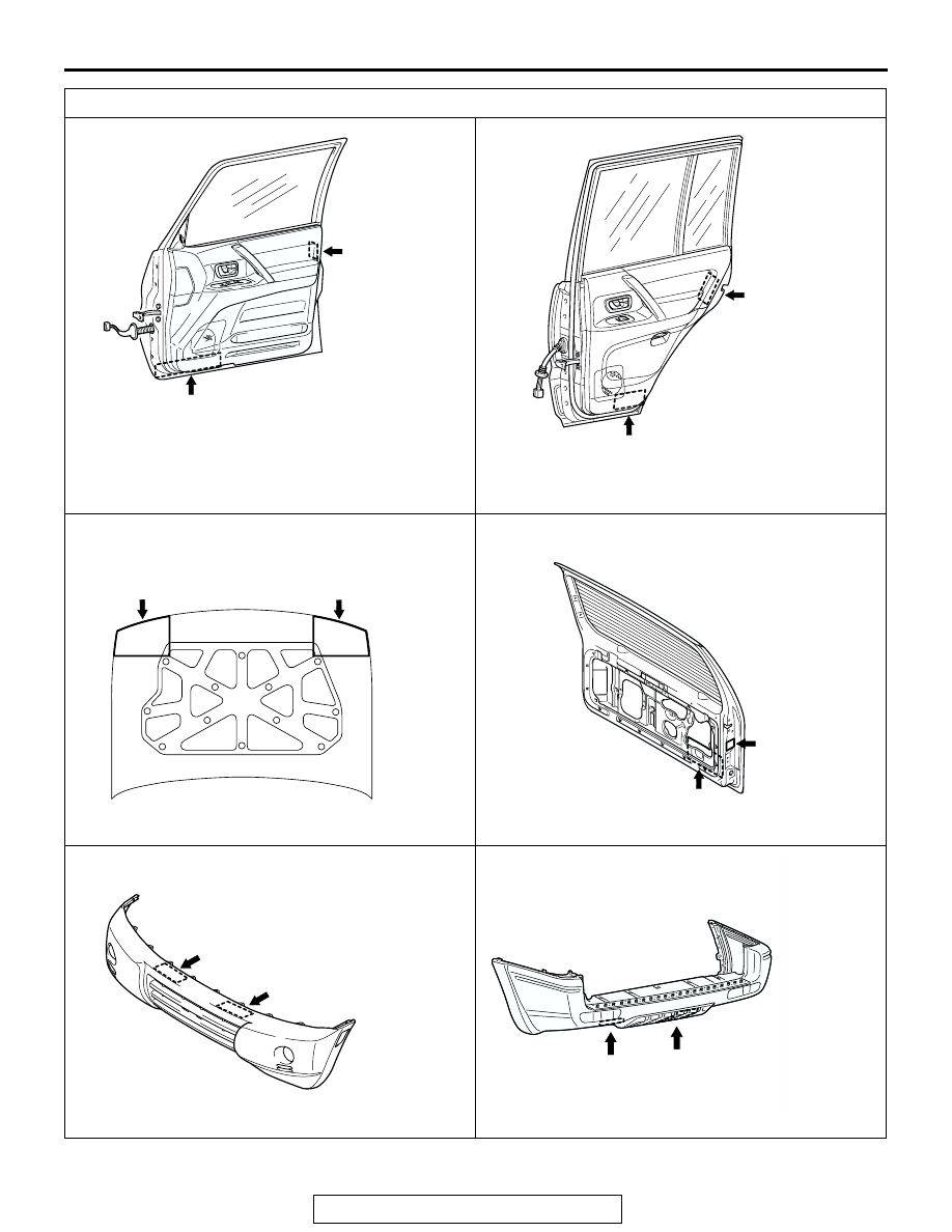
TARGET AREA (A: FOR ORIGINAL EQUIPMENT PARTS, B: FOR REPLACEMENT PARTS)

ACX01194

A

B

AB

FRONT DOOR

The illustration indicates right outer side.
Left side is symmetrically opposite.

ACX01195

A

B

REAR DOOR

The illustration indicates right outer side.
Left side is symmetrically opposite.

AB

ACX01196

A

B

HOOD

AB

ACX01197 AB

B

A

BACK DOOR

AC203795

AB

FRONT BUMPER

A

B

AC203796

AB

REAR BUMPER

A

B

PRECAUTIONS BEFORE SERVICE

TSB Revision

GENERAL <BODY AND CHASSIS>

00-22

PRECAUTIONS BEFORE SERVICE

M1001000500486

SUPPLEMENTAL RESTRAINT SYSTEM 
(SRS)

1. Items to follow when servicing SRS

(1) Be sure to read GROUP 52B, Supplemental 

Restraint System (SRS). For safe operation, 
please follow the directions and heed all 
warnings.

(2) Wait at least 60 seconds after disconnecting 

the battery cable before doing any further 
work. The SRS system is designed to retain 
enough voltage to deploy the air bag even 
after the battery has been disconnected. 
Serious injury may result from unintended air 
bag deployment if work is done on the SRS 
system immediately after the battery cable is 
disconnected.

(3) Warning labels must be heeded when 

servicing or handling SRS components. 
Warning labels can be found in the following 
locations.

• Hood

• Front impact sensor, side impact sensor

• Sun visor

• Glove box

• SRS-ECU

• Steering wheel

• Air bag module, side−airbag modules

• Clock spring

• Steering gear box

• Seat belt pre-tensioner

(4) Always use the designated special tools and 

test equipment.

(5) Store components removed from the SRS in a 

clean and dry place. The air bag module 
should be stored on a flat surface and placed 
so that the pad surface is facing upward.

(6) Never attempt to disassemble or repair the 

SRS components (SRS-ECU, air bag module, 
clock spring and seat belt pre-tensioner). If 
there is a defect, replace the defective part.

(7) Whenever you finish servicing the SRS, check 

the SRS warning light operation to make sure 
that the system functions properly.

(8) Be sure to deploy the air bag before disposing 

of the air bag module or disposing of a vehicle 
equipped with an air bag. (Refer to GROUP 
52B, Air Bag Module Disposal Procedures 

P.52B-234

.)

2. Observe the following when carrying out 

operations on places where SRS components are 
installed, including operations not directly related 
to the SRS air bag.
(1) When removing or installing parts, do not allow 

any impact or shock to the SRS components.

(2) If heat damage may occur during paint work, 

remove the SRS components. After 
re-installing them, check the SRS warning light 
operation to make sure that the system 
functions properly.

• • SRS-ECU, air bag module, clock spring: 93°C 

(200

°F) or more

• • Seat belt pre-tensioner: 90°C (194°F) or more

SERVICING ELECTRICAL SYSTEM

WARNING

Battery posts, terminals and related accessories con-
tain lead and lead compounds. WASH HANDS AFTER 
HANDLING.

1. Note the following before proceeding with working on the 

electrical system. 
Never perform unauthorized modifications to any electrical 
device or wiring. Such modifications might lead to a vehicle 
malfunction, over-capacity or short-circuit that could result in 
a fire in the vehicle.

ACX00880AB

PRECAUTIONS BEFORE SERVICE

TSB Revision

GENERAL <BODY AND CHASSIS>

00-23

CAUTION

• Before connecting or disconnecting the negative bat-

tery cable, be sure to turn off the ignition switch and 
the lights. (If this is not done, there is the possibility of 
semiconductor parts being damaged.)

• After completion of the work steps (when the negative 

battery terminal is connected), warm up the engine and 
allow it to idle for approximately 10 minutes under the 
conditions described below in order to stabilize engine 
control conditions, and then check to be sure that the 
idling is satisfactory.

2. When servicing the electrical system, disconnect the 

negative cable terminal from the battery.

Engine coolant temperature: 85 

 95°C (185  203°F)

Lights and all accessories: OFF
Transmission: N or P position 
Steering wheel: straight-forward position

VEHICLE WASHING

If high-pressure car-washing equipment or steam car-washing 
equipment is used to wash the vehicle, be sure to maintain the 
spray nozzle at a distance of at least approximately 40cm (16 
inches) from any plastic parts and all opening parts (doors, lug-
gage compartment, etc.).

APPLYING ANTI-CORROSION AGENT OR OTHER 
UNDERCOAT AGENTS

Be careful not to adhere oil or grease to the heated oxygen 
sensor. If adhered, the sensor may malfunction. Protect the 
heated oxygen sensor with a cover before applying anti-corro-
sion agent, etc.

SCAN TOOL (MUT-III Sub Assembly)

CAUTION

Turn the ignition switch to the "LOCK" (OFF) position 
before disconnecting or connecting the scan tool.
NOTE: MUT-III Trigger Harness is not necessary when pushing 
V.C.I. ENTER key.

ACX00881AB

APPROXIMATELY
40 cm (16 in)

PRECAUTIONS BEFORE SERVICE

TSB Revision

GENERAL <BODY AND CHASSIS>

00-24

AC2010881

MB991910

MB991826

MB991911

MB991825

MB991824

MB991827

MB991914

AC

VEHICLE COMMUNICATION 
INTERFACE (V.C.I.)

MUT-III MAIN HARNESS A

MUT-III USB CABLE

MUT-III MAIN HARNESS B

MUT-III MAIN HARNESS C

MUT-III MEASUREMENT ADAPTER

MUT-III TRIGGER HARNESS 

DO NOT USE

DO NOT USE


Content   ..  5  6  7  8   ..