Mitsubishi Montero (2002-2004). Manual - part 976


  Index      Mitsubishi     Mitsubishi Montero - service repair manual 2002-2004 year


Search            


Content   ..  974  975  976  977   ..


Mitsubishi Montero (2002-2004). Manual - part 976


SYMPTOM PROCEDURES <AUTOMATIC TRANSMISSION>

TSB Revision

SYMPTOM PROCEDURES

23Ad-15

STEP 4. Check the hydraulic pressure (for low-reverse 
brake).
Measure the hydraulic pressure for low-reverse brake when the 
selector lever is at the "R" range. Check if the hydraulic pres-
sure is within the standard value. Refer to 

P.23Ab-15

, Hydraulic 

Pressure Test.
Q: Is the hydraulic pressure within the standard value?

YES : Go to Step 5.
NO :  Go to Step 9.

STEP 5. Check the reverse clutch system and low-reverse 
brake system.
(1) Remove the valve body cover and valve body. Refer to 

P.23Aa-37

, Transmission and Transfer Assembly and refer 

to GROUP 23B, Transmission 

P.23B-18

.

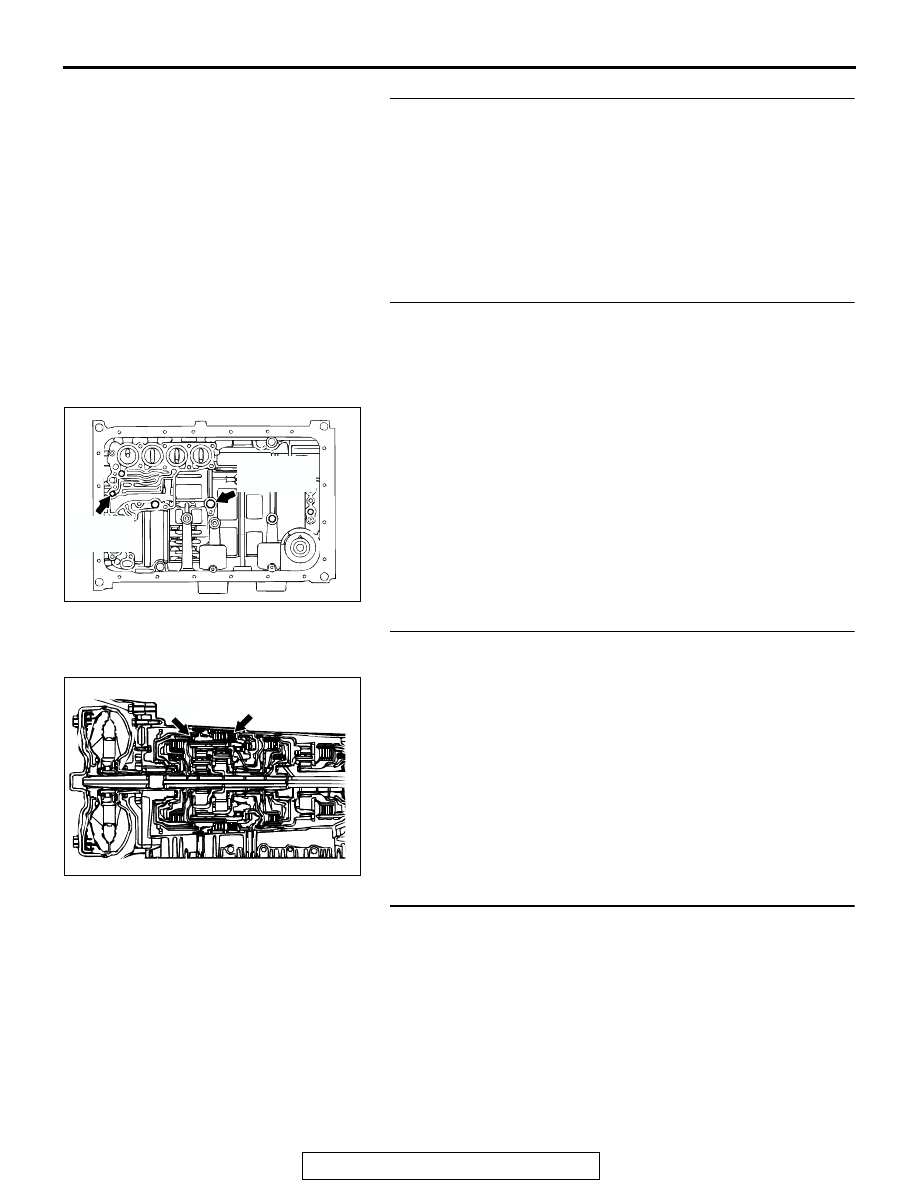
(2) Blow 108 kPa (15 psi) compressed air into the reverse 

clutch oil orifice of the transmission case, and check if the 
reverse clutch piston moves and air pressures are 
maintained in that condition. Repeat for the low-reverse 
brake.

Q: Are both air pressures maintained?

YES : Go to Step 6.
NO :  Go to Step 9.

STEP 6. Check the reverse clutch and low-reverse brake.
(1) Remove the transmission assembly.
(2) Check the facing for seizure and the piston seal ring for 

damage and interference with the retainer. Repair or 
replace the faulty parts. Refer to GROUP 23B, 
Transmission 

P.23B-18

, Reverse and Overdrive Clutch 

P.23B-67

. Then check for the symptom.

Q: Is the symptom eliminated?

YES : The procedure is complete.
NO :  Go to Step 10.

STEP 7. Check shift shock.
Q: Does shift shock occur sometimes?

YES : Go to Step 8.
NO :  Go to Step 9.

ACX02249AC

REVERSE
CLUTCH OIL
ORIFICE

LOW-REVERSE
BRAKE OIL
ORIFICE

AC204883

REVERSE
CLUTCH

LOW-REVERSE
BRAKE

AC

SYMPTOM PROCEDURES <AUTOMATIC TRANSMISSION>

TSB Revision

SYMPTOM PROCEDURES

23Ad-16

STEP 8. Using scan tool MB991502, check data list item 11: 
APP sensor.

CAUTION

To prevent damage to scan tool MB991502, always turn the 
ignition switch to the "LOCK" (OFF) position before con-
necting or disconnecting scan tool MB991502.
(1) Connect scan tool MB991502 to the data link connector.
(2) Turn the ignition switch to the "ON" position.
(3) Set scan tool MB991502 to data reading mode for item 11, 

APP Sensor.

• With the throttle valve in the idle position, voltage should 

measure between 535 and 735 mV.

• With the throttle valve in the full-open position, voltage 

should measure between 4,500 and 5,500 mV.

(4) Turn the ignition switch to the "LOCK" (OFF) position.
Q: Is the measured voltage between 535 and 735mV at idle, 

and between 4,500 and 5,500 mV in the full-open 
position? 
YES : 
Go to Step 10.
NO :  Go to Step 9.

STEP 9. Using scan tool MB991502, read the MFI 
diagnostic trouble code.
(1) Connect scan tool MB991502 to the data link connector.
(2) Turn the ignition switch to the "ON" position.
(3) Check for MFI diagnostic trouble code.
(4) Turn the ignition switch to the "LOCK" (OFF) position.
Q: Are MFI DTC Nos. of TP sensor system set?

YES : Refer to GROUP 13A, Diagnosis 

− Diagnostic 

Trouble Code Chart 

P.13Ab-22

.

NO :  Go to Step 11.

STEP 10. Disassemble and clean the valve body.
Check the O-ring installation bolts for looseness and the valve 
body for damage. Repair or replace the faulty parts. Refer to 
GROUP 23B, Valve Body 

P.23B-80

.

Replace the valve body assembly if the damages are thought 
to be irreparable. Then check the symptom.
Q: Is the symptom eliminated?

YES : The procedure is complete.
NO :  Go to Step 11.

STEP 11. Replace the PCM.
Q: Is the symptom eliminated?

YES : The procedure is complete.
NO :  Start over at Step 1.

ACX01539AD

MB991502

16-PIN

ACX01539AD

MB991502

16-PIN

ACX02161AD

VALVE BODY ASSEMBLY

SYMPTOM PROCEDURES <AUTOMATIC TRANSMISSION>

TSB Revision

SYMPTOM PROCEDURES

23Ad-17

INSPECTION PROCEDURE 8: Shift Shock when Shifting from "N" to "D," "N" to "R" and Long Delay

.

COMMENT
If abnormal shock or delay of two seconds or more 
occurs when the selector lever is moved from "N" to 
"D" range and from "N" to "R" range while the engine 
is idling, the cause is probably abnormal line pres-
sure or a malfunction of the oil pump or valve body.

.

TROUBLESHOOTING HINTS (The most likely 
causes for this case:)

• Abnormal line pressure

• Malfunction of the oil pump

• Malfunction of the valve body

• Malfunction of the PCM

DIAGNOSIS

STEP 1. Check the hydraulic pressure.
(1) Measure the hydraulic pressure of each element when the 

transmission is in 1st, 2nd or reverse. Check if each 
hydraulic pressure is within the standard value. Refer to 

P.23Ab-15

Hydraulic Pressure Test.

(2) If some elements are within the standard value and some 

are not, recheck the symptom.

Q: Are all hydraulic pressures within the standard value?

YES : Go to Step 3.
NO :  Go to Step 2.

STEP 2. Adjust line pressure.
Adjust line pressure. Refer to 

P.23Ab-31

, Line Pressure Adjust-

ment. Then check the symptom.
Q: Is the symptom eliminated?

YES : The procedure is complete.
NO :  Go to Step 3.

STEP 3. Check when shift shock occurs.
Q: When does the shift shock occur?

When engaging from "N" to "D" and "N" to "R" : Go to 

Step 4.

When the vehicle starts moving : Go to Step 5.

STEP 4. Replace the oil pump.
(1) Remove the transmission.
(2) Replace the oil pump. (Oil pump cannot be repaired). Refer 

to GROUP 23B, Transmission 

P.23B-18

. Then check the 

symptom.

Q: Is the symptom eliminated?

YES : The procedure is complete.
NO :  Go to Step 6.

AC204883 AD

SYMPTOM PROCEDURES <AUTOMATIC TRANSMISSION>

TSB Revision

SYMPTOM PROCEDURES

23Ad-18

STEP 5. Disassemble and clean the valve body.
Check the installation bolts for looseness and the O-ring, 
valves and valve body for damage. Repair or replace the faulty 
parts. Refer to GROUP 23B, Valve Body 

P.23B-80

.

Replace the valve body assembly if the damages are thought 
to be irreparable. Then check the symptom.
Q: Is the symptom eliminated?

YES : The procedure is complete.
NO :  Go to Step 6.

STEP 6. Replace the PCM.
Q: Is the symptom eliminated?

YES : The procedure is complete.
NO :  Start over at Step 1.

INSPECTION PROCEDURE 9: Shift Shock and Slipping

.

COMMENT
If shift shock when driving are due to upshifting or 
downshifting and the transmission speed become 
higher than the engine speed, the cause is probably 
abnormal line pressure or a malfunction of a solenoid 
valve, oil pump, valve body or of a brake or clutch.

.

TROUBLESHOOTING HINTS (The most likely 
causes for this case:)

• Abnormal line pressure

• Malfunction of each solenoid valve

• Malfunction of the oil pump

• Malfunction of the valve body

• Malfunction of each brake or each clutch

• Malfunction of the PCM

ACX02161AD

VALVE BODY ASSEMBLY


Content   ..  974  975  976  977   ..