Mitsubishi Montero (2002-2004). Manual - part 955


  Index      Mitsubishi     Mitsubishi Montero - service repair manual 2002-2004 year


Search            


Content   ..  953  954  955  956   ..


Mitsubishi Montero (2002-2004). Manual - part 955


DIAGNOSTIC TROUBLE CODE PROCEDURES <TRANSFER>

TSB Revision

DIAGNOSTIC TROUBLE CODE PROCEDURES

23Ac-303

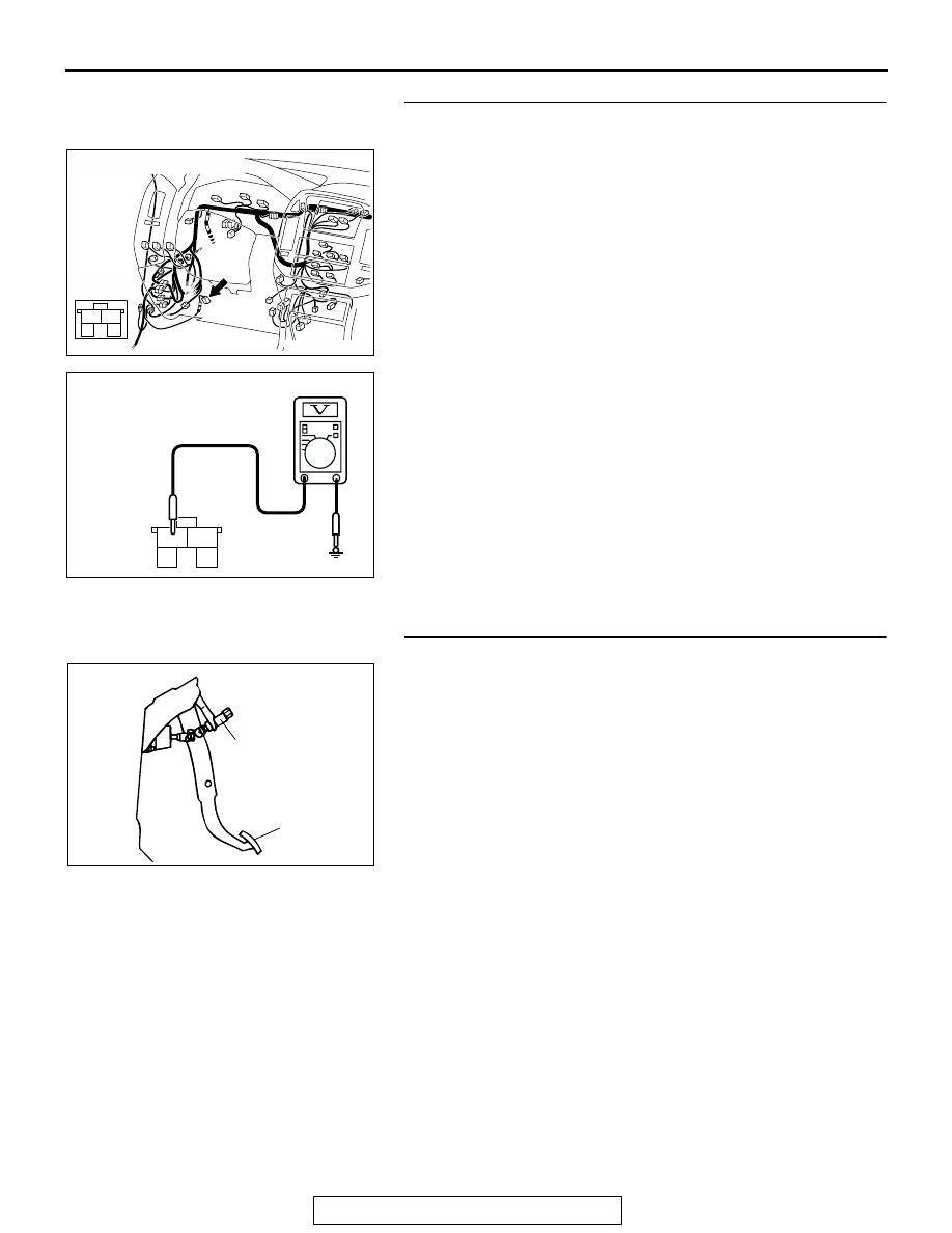
STEP 6. Measure the stoplight switch output voltage to the 
PCM at connector D-123 by backprobing.
(1) Remove the stoplight switch from the mounting bracket.
(2) Do not disconnect connector D-123.

(3) Measure the voltage between stoplight switch connector D-

123 terminal 1 and ground by backprobing.

• When the switch button is out (closed circuit), voltage 

should equal battery positive voltage.

• When the switch button is depressed (open circuit), volt-

age should measure less than 1.0 volt.

Q: Is the measured voltage battery positive voltage with 

the switch button released (closed circuit), and less 
than 1.0 volt with the switch button depressed (open 
circuit)?
YES : 
Go to Step 8.
NO :  Go to Step 7.

STEP 7. Check the stoplight switch.
Refer to GROUP 35A, On-vehicle Service 

− Stoplight Switch 

Check 

P.35A-116

.

Q: Does the stoplight switch pass the checks?

YES : Go to Step 8.
NO :  Replace the stoplight switch. Refer to GROUP 35A, 

Brake Pedal 

P.35A-132

.

AC204170

CONNECTOR : D-123

CG

4

2

3

1

AC204918 BA

D-123 HARNESS CONNECTOR : 
HARNESS SIDE

4

2

3

1

ACX02208

BRAKE PEDAL

STOPLIGHT
SWITCH

AD

DIAGNOSTIC TROUBLE CODE PROCEDURES <TRANSFER>

TSB Revision

DIAGNOSTIC TROUBLE CODE PROCEDURES

23Ac-304

STEP 8. Measure the stoplight switch output voltage at 
transfer-ECU connector E-104 by backprobing.
(1) Install the stoplight switch into the mounting bracket if it was 

removed.

(2) Do not disconnect connector E-104.

(3) Measure the voltage between terminal 34 and ground by 

backprobing.

• When the brake pedal is depressed, voltage should 

measure battery positive voltage.

• When the brake pedal is not depressed, voltage should 

measure less than 1.0 volt.

Q: Is the measured voltage battery positive voltage with 

the brake pedal depressed (closed circuit), and less 
than 1.0 volt with the brake pedal released (open 
circuit)?
YES : 
Go to Step 11.
NO :  Go to Step 9.

AC204176

CONNECTOR : E-104

BA

51

40

3839

50

41

52

48

37

46

35

47

36

45

34

43

32

44

33

49

42

31

AC204918 BV

E-104 HARNESS CONNECTOR : 
HARNESS SIDE

51

40

3839

50

41

52

48

37

46

35

47

36

45

34

43

32

44

33

49

42

31

DIAGNOSTIC TROUBLE CODE PROCEDURES <TRANSFER>

TSB Revision

DIAGNOSTIC TROUBLE CODE PROCEDURES

23Ac-305

STEP 9. Check joint connector D-29, intermediate 
connector D-125, E-11 and transfer-ECU connector E-104 
for loose, corroded or damaged terminals, or terminals 
pushed back in the connector.
Q: Are the connectors and terminals in good condition?

YES : Go to Step 10.
NO :  Repair or replace the damaged components. Refer to 

GROUP 00E, Harness Connector Inspection 

P.00E-

2

.

AC204188

CONNECTORS : D-29, D-125

D-29

BA

D-125

D-125

D-29

9

8

6 7

5

3 4

20

32

21

33

43

17 18

30

41

16

29

28

39 40

13

25

12

24

35 36

14

26

37

15

27

38

19

31

42

1

10

22

2

11

23

34

9 10

8

6 7

31 32

30

29

18 19 20 21

5

4

2

1

3

27

26

24

23

25

12 13 14 15 16 17

28

11
22
33

AC204194

CONNECTORS : E-11, E-104

E-104

E-104

E-11

E-11

AV

51

40

3839

50

41

52

48

37

46

35

47

36

45

34

43

32

44

33

49

42

31

3

10

16

9

7 8

6

1

4

2

5

11

14

1213

15

DIAGNOSTIC TROUBLE CODE PROCEDURES <TRANSFER>

TSB Revision

DIAGNOSTIC TROUBLE CODE PROCEDURES

23Ac-306

STEP 10. Check the harness for open circuit or short 
circuit to ground between stoplight switch connector D-
123 terminal 1 and transfer-ECU connector E-104 terminal 
34.
Q: Is the harness wire in good condition?

YES : Go to Step 11.
NO :  Repair or replace the harness wire.

STEP 11. Using scan tool MB991502, check data list item 
23: Stoplight Switch.

CAUTION

To prevent damage to scan tool MB991502, always turn the 
ignition switch to the "LOCK" (OFF) position before con-
necting or disconnecting scan tool MB991502.
(1) Connect scan tool MB991502 to the data link connector.
(2) Turn the ignition switch to the "ON" position.
(3) Set scan tool MB991502 to data reading mode for item 23, 

Stoplight Switch 

− Active Trac 4WD II.

• When the brake pedal is depressed, the display on scan 

tool MB991502 should be "ON."

• When the brake pedal is not depressed, the display on 

scan tool MB991502 should be "OFF."

(4) Turn the ignition switch to the "LOCK" (OFF) position.
Q: Is the switch operating properly?

YES : If can be assumed that this malfunction is intermittent. 

Refer to GROUP 00, How to Use Troubleshooting/
Inspection Service Points 

− How to Cope with 

Intermittent Malfunction 

P.00-6

.

NO :  Replace the PCM.

AC204170

CONNECTOR : D-123

CG

4

2

3

1

AC204176

CONNECTOR : E-104

BA

51

40

3839

50

41

52

48

37

46

35

47

36

45

34

43

32

44

33

49

42

31

ACX01539AD

MB991502

16-PIN


Content   ..  953  954  955  956   ..