Mitsubishi Montero (2002-2004). Manual - part 939


  Index      Mitsubishi     Mitsubishi Montero - service repair manual 2002-2004 year


Search            


Content   ..  937  938  939  940   ..


Mitsubishi Montero (2002-2004). Manual - part 939


DIAGNOSTIC TROUBLE CODE PROCEDURES <AUTOMATIC TRANSMISSION>

TSB Revision

DIAGNOSTIC TROUBLE CODE PROCEDURES

23Ac-239

DIAGNOSIS

Required Special Tool:

• MB991502: Scan Tool (MUT-II)

STEP 1. Using scan tool MB991502, check data list item 54: 
A/T Control Relay Output Voltage.

CAUTION

To prevent damage to scan tool MB991502, always turn the 
ignition switch to the "LOCK" (OFF) position before con-
necting or disconnecting scan tool MB991502.
(1) Connect scan tool MB991502 to the data link connector.
(2) Turn the ignition switch to the "ON" position.
(3) Set scan tool MB991502 to data reading mode for item 54, 

A/T Control Relay Output Voltage.

• The voltage should equal battery positive voltage.

(4) Turn the ignition switch to the "LOCK" (OFF) position.
Q: Is the measured voltage equal battery positive voltage?

YES : It can be assumed that this malfunction is intermittent. 

Refer to GROUP 00, How to Use Troubleshooting/
Inspection Service Points 

− How to Cope with 

Intermittent Malfunction 

P.00-6

.

NO :  Go to Step 2.

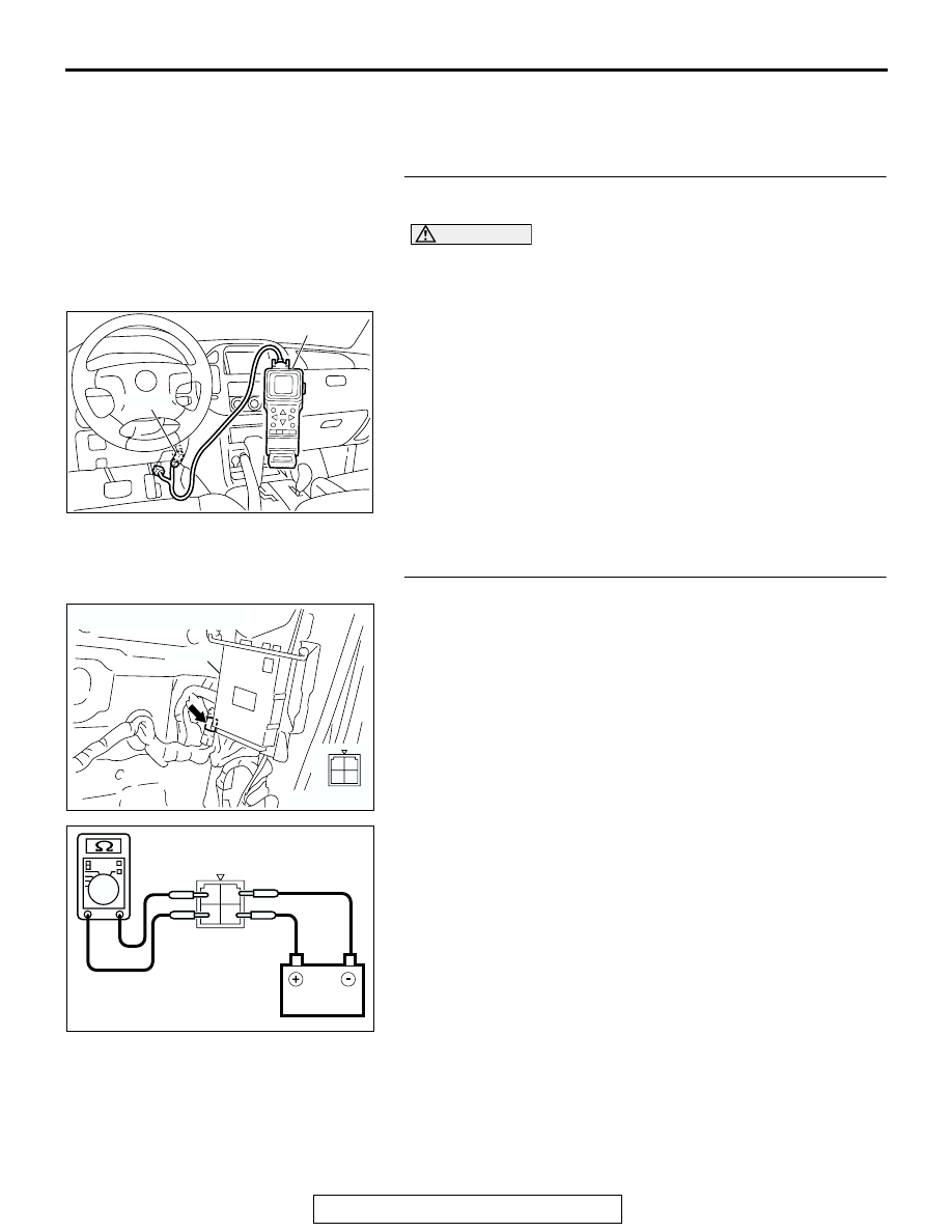
STEP 2. Check the A/T control relay.
(1) Remove the A/T control relay (A/T control relay connector 

D-13).

(2) Using jumper wires, connect terminal 2 to the negative 

battery terminal, and terminal 4 to the positive battery 
terminal.

(3) Measure the resistance between terminal 1 and 3 of the A/T 

control relay.

• The resistance should measure less than 2 ohms.

•  Disconnect the jumper wires. The resistance between 

terminals 1 and 3 should measure over limits (open cir-
cuit).

Q: Does the resistance measure less than 2 ohms when the 

relay is energized, and open circuit when the relay is de-
energized?
YES : 
Go to Step 3.
NO :  Replace the A/T control relay.

ACX01539AD

MB991502

16-PIN

AC204750

CONNECTOR : D-13

AB

PCM

1
3 4

2

AC204947

1
3 4

2

D-13 HARNESS CONNECTOR : 
A/T CONTROL RELAY SIDE

AB

DIAGNOSTIC TROUBLE CODE PROCEDURES <AUTOMATIC TRANSMISSION>

TSB Revision

DIAGNOSTIC TROUBLE CODE PROCEDURES

23Ac-240

STEP 3. Check A/T control relay connector D-13 for loose, 
corroded or damaged terminals, or terminals pushed back 
in the connector.
Q: Are the connector and terminals in good condition?

YES : Go to Step 4.
NO :  Repair or replace the damaged components. Refer to 

GROUP 00E, Harness Connector Inspection 

P.00E-

2

.

STEP 4. Measure the supply voltage at A/T control relay 
connector D-13.
(1) Disconnect the A/T control relay and measure at the 

harness side.

(2) Measure the voltage between terminal 1 and ground.

• The measured voltage should equal battery positive 

voltage.

Q: Is the measured voltage equal to battery positive 

voltage?
YES : 
Go to Step 7.
NO :  Go to Step 5.

AC204750

CONNECTOR : D-13

AB

PCM

1
3 4

2

AC204750

CONNECTOR : D-13

AB

PCM

1
3 4

2

AC204918

D-13 HARNESS CONNECTOR :
COMPONENT SIDE

DF

1
3

4

2

DIAGNOSTIC TROUBLE CODE PROCEDURES <AUTOMATIC TRANSMISSION>

TSB Revision

DIAGNOSTIC TROUBLE CODE PROCEDURES

23Ac-241

STEP 5. Check intermediate connector A-03 for loose, 
corroded or damaged terminals, or terminals pushed back 
in the connector.
Q: Are the connector and terminals in good condition?

YES : Go to Step 6.
NO :  Repair or replace the damaged components. Refer to 

GROUP 00E, Harness Connector Inspection 

P.00E-

2

.

STEP 6. Check the harness for open circuit or short circuit 
to ground between A/T control relay connector D-13 
terminal 1 and battery.
Q: Is the harness wire in good condition?

YES : Go to Step 19.
NO :  Repair or replace the harness wire.

AC204167

CONNECTOR : A-03

AT

A-03 (B)

6

12

5

3 4

2

1

9 10

8

7

11

AC204750

CONNECTOR : D-13

AB

PCM

1
3 4

2

DIAGNOSTIC TROUBLE CODE PROCEDURES <AUTOMATIC TRANSMISSION>

TSB Revision

DIAGNOSTIC TROUBLE CODE PROCEDURES

23Ac-242

STEP 7. Measure the resistance at A/T control relay 
connector D-13.
(1) Disconnect the A/T control relay and measure at the 

harness side.

(2) Measure the resistance between terminal 2 and ground.

• The resistance should measure less than 2 ohms.

Q: Is the measured resistance less than 2 ohms?

YES : Go to Step 10.
NO :  Go to Step 8.

STEP 8. Check ground joint connector D-14 for loose, 
corroded or damaged terminals, or terminals pushed back 
in the connector.
Q: Are the connector and terminals in good condition?

YES : Go to Step 9.
NO :  Repair or replace the damaged components. Refer to 

GROUP 00E, Harness Connector Inspection 

P.00E-

2

.

AC204750

CONNECTOR : D-13

AB

PCM

1
3 4

2

AC204918

D-13 HARNESS CONNECTOR :
COMPONENT SIDE

DG

1
3

4

2

AC204171

CONNECTOR : D-14

AM

4

9

8

6

5

7

1 2

3

10


Content   ..  937  938  939  940   ..