Mitsubishi Montero (2002-2004). Manual - part 922


  Index      Mitsubishi     Mitsubishi Montero - service repair manual 2002-2004 year


Search            


Content   ..  920  921  922  923   ..


Mitsubishi Montero (2002-2004). Manual - part 922


DIAGNOSTIC TROUBLE CODE PROCEDURES <AUTOMATIC TRANSMISSION>

TSB Revision

DIAGNOSTIC TROUBLE CODE PROCEDURES

23Ac-171

DTC 33: Second Solenoid Valve System

.

Solenoid Valve System Circuit
Refer to 

P.23Ac-147

.

.

CIRCUIT OPERATION
Refer to 

P.23Ac-147

.

.

DTC SET CONDITIONS
If the resistance value for the second solenoid valve 
circuit is greater than 3.5 ohms (open) or less than 
2.6 ohms (short) for 4 seconds, DTC 33 is set. The 
transmission is locked into 3rd gear as a fail-safe 
measure, and the "N" range light flashes once per 
second.

.

TROUBLESHOOTING HINTS (The most likely 
causes for this code to be set are:)

• Malfunction of second solenoid valve

• Damaged harness, connector

• Malfunction of the PCM

DIAGNOSIS

Required Special Tool:

• MB991502: Scan Tool (MUT-II)

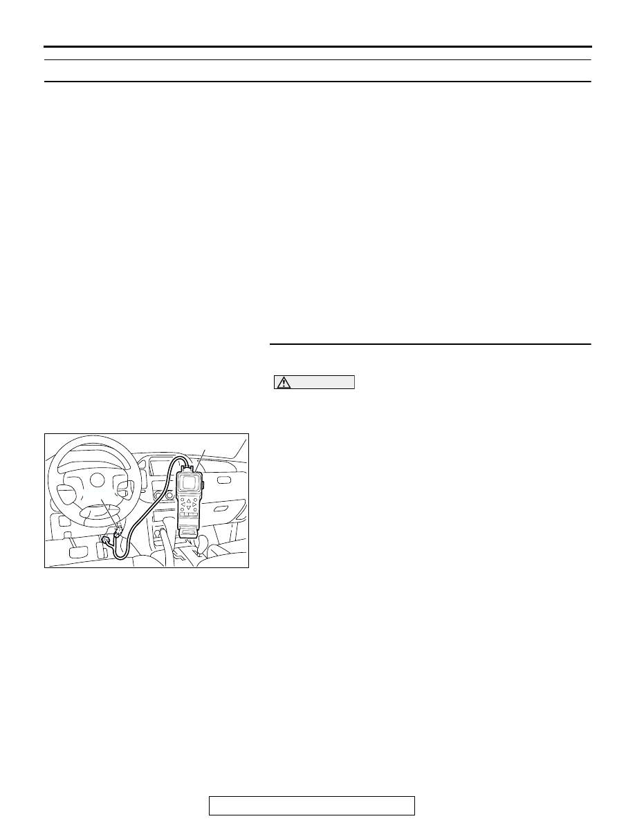
STEP 1. Using scan tool MB991502, check actuator test 
item 03: Second Solenoid Valve.

CAUTION

To prevent damage to scan tool MB991502, always turn the 
ignition switch to the "LOCK" (OFF) position before con-
necting or disconnecting scan tool MB991502.
(1) Connect scan tool MB991502 to the data link connector.
(2) Turn the ignition switch to the "ON" position.
(3) Set scan tool MB991502 to actuator test mode for item 03, 

Second Solenoid Valve.

• An audible clicking or buzzing should be heard when the 

second solenoid valve is energized.

(4) Turn the ignition switch to the "LOCK" (OFF) position.
Q: Is the solenoid valve operating properly?

YES : It can be assumed that this malfunction is intermittent. 

Refer to GROUP 00, How to Use Troubleshooting/
Inspection Service Points 

− How to Cope with 

Intermittent Malfunctions 

P.00-6

.

NO :  Go to Step 2.

ACX01539AD

MB991502

16-PIN

DIAGNOSTIC TROUBLE CODE PROCEDURES <AUTOMATIC TRANSMISSION>

TSB Revision

DIAGNOSTIC TROUBLE CODE PROCEDURES

23Ac-172

STEP 2. Using scan tool MB991502, read the A/T 
diagnostic trouble code.
(1) Connect scan tool MB991502 to the data link connector.
(2) Turn the ignition switch to the "ON" position.
(3) Check for A/T diagnostic trouble code.
(4) Turn the ignition switch to the "LOCK" (OFF) position.
Q: Is DTC 54 set? (DTC 54 may be set along with multiple 

DTCs.)
YES : 
Refer to 

P.23Ac-237

 DTC 54: A/T Control Relay 

System.

NO :  Go to Step 3.

STEP 3. Using scan tool MB991502, read the A/T 
diagnostic trouble code.
(1) Connect scan tool MB991502 to the data link connector.
(2) Turn the ignition switch to the "ON" position.
(3) Check for A/T diagnostic trouble code.
(4) Turn the ignition switch to the "LOCK" (OFF) position.
Q: Are DTC 32 and DTC 34 set? (Multiple DTCs may be set.)

YES : Go to Step 8.
NO :  Go to Step 4.

STEP 4. Measure the second solenoid valve resistance at 
A/T control solenoid valve assembly connector C-03.
(1) Disconnect connector C-03 and measure at the solenoid 

valve side.

(2) Measure the resistance between solenoid valve assembly 

connector C-03 terminals 4 and 9.

Resistance value: 2.7 

 3.4 ohms [at 20°C (68°F)]

Q: Is the measured resistance 2.7 

 3.4 ohms [at 20°

(68

°F)]?

YES : Go to Step 6.
NO :  Go to Step 5.

ACX01539AD

MB991502

16-PIN

ACX01539AD

MB991502

16-PIN

AC204395

CONNECTOR : C-03

AE

C-03 (B)

6

10

4

9

5

3

8

2

7

1

AC204918

C-03 HARNESS CONNECTOR : 
SOLENOID VALVE SIDE

CU

6

10

4

9

5

3

8

2

7

1

DIAGNOSTIC TROUBLE CODE PROCEDURES <AUTOMATIC TRANSMISSION>

TSB Revision

DIAGNOSTIC TROUBLE CODE PROCEDURES

23Ac-173

STEP 5. Measure the solenoid valve resistance at the 
second solenoid valve connector C-03-3 inside the 
transmission.
(1) Disconnect solenoid valve connector C-03-3 and measure 

at the solenoid valve side.

(2) Measure the resistance between second solenoid valve 

terminals 1 and 2.

Resistance value: 2.7 

 3.4 ohms [at 20°C (68°F)]

Q: Is the measured resistance 2.7 

 3.4 ohms [at 20°

(68

°F)?

YES : Replace the harness wire between A/T control 

solenoid valve assembly connector C-03 and the 
solenoid valves.

NO :  Replace the second solenoid valve. Refer to GROUP 

23B, Valve Body 

P.23B-80

.

AC204748

CONNECTOR : C-03-3

AD

1
2

AC204918

C-03-3 HARNESS CONNECTOR : 
SECOND SOLENOID 
VALVE SIDE

CO

1
2

DIAGNOSTIC TROUBLE CODE PROCEDURES <AUTOMATIC TRANSMISSION>

TSB Revision

DIAGNOSTIC TROUBLE CODE PROCEDURES

23Ac-174

STEP 6. Check A/T control solenoid valve assembly 
connector C-03, PCM connector D-136 and intermediate 
connector E-114 for loose, corroded or damaged 
terminals, or terminals pushed back in the connector.
Q: Are the connectors and terminals in good condition?

YES : Go to Step 7.
NO :  Repair or replace the damaged components. Refer to 

GROUP 00E, Harness Connector Inspection 

P.00E-

2

.

AC204395

CONNECTOR : C-03

AE

C-03 (B)

6

10

4

9

5

3

8

2

7

1

AC204681AD

CONNECTOR: D-136

D-136 (GR)

121 122

123

124

125 126 127 128 129 130

131 132

133

134 135

136 137 138

139 140

141

142 143

144

145

146

AC204176

CONNECTOR : E-114

BD

38

28

16

33

22

10

31

19

7

1

18

30

29

17

5

6

21

20

32

8

2

9

25

13

3

24

23

3435

1112

27

26

3637

14

4

15


Content   ..  920  921  922  923   ..