Mitsubishi Montero (2002-2004). Manual - part 908


  Index      Mitsubishi     Mitsubishi Montero - service repair manual 2002-2004 year


Search            


Content   ..  906  907  908  909   ..


Mitsubishi Montero (2002-2004). Manual - part 908


DIAGNOSTIC TROUBLE CODE PROCEDURES <AUTOMATIC TRANSMISSION>

TSB Revision

DIAGNOSTIC TROUBLE CODE PROCEDURES

23Ac-115

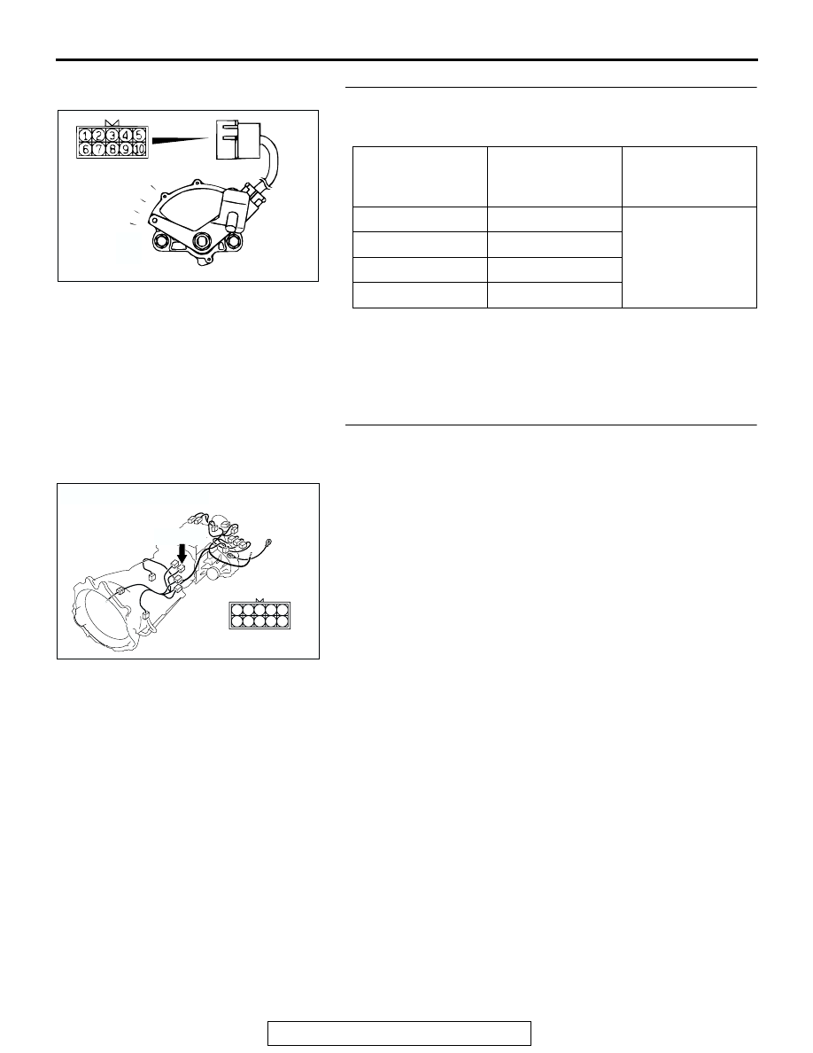
STEP 28. Check the transmission range switch.
Measure the resistance between the terminals for each selec-
tor position as indicated in the tables above.

Q: Does the resistance measure less than 2 ohms for each 

selector position?
YES : 
Go to Step 29.
NO :  Replace the transmission range switch. Refer to 

GROUP 23B, Transmission 

P.23B-18

.

STEP 29. Check transmission range switch connector C-04 
for loose, corroded or damaged terminals, or terminals 
pushed back in the connector.
Q: Is the connector in good condition?

YES : Go to Step 30.
NO :  Repair or replace the damaged components. Refer to 

GROUP 00E, Harness Connector Inspection 

P.00E-

2

.

TRANSMISSION 
RANGE

TERMINAL 
CONNECTION OF 
TESTER

SPECIFIED 
CONDITION

P

− 7

Less than 2 ohms.

R

− 8

N

− 7

D

− 7

ACX01187AD

P

R

N

D

AC204395

CONNECTOR : C-04

AF

C-04 (B)

4
9

5

10

3
8

2
7

6

1

DIAGNOSTIC TROUBLE CODE PROCEDURES <AUTOMATIC TRANSMISSION>

TSB Revision

DIAGNOSTIC TROUBLE CODE PROCEDURES

23Ac-116

STEP 30. Measure the transmission range switch output 
voltage at PCM connector D-134 by backprobing.
(1) Do not disconnect connector D-134.
(2) Turn the ignition switch to the "ON" position.
(3) Move the selector lever to the "D" position.

(4) Measure the voltage between terminal 76 and ground by 

backprobing.

• The voltage should measure battery positive voltage.

(5) Turn the ignition switch to the "LOCK" (OFF) position.
Q: Does the voltage measure battery positive voltage?

YES : Go to Step 13.
NO :  Go to Step 31.

AC204681AC

CONNECTOR: D-134

D-134 (GR)

61 62

63 64

65 66 67 68 69 70 71 72 73

82

89

81

88

80

79

78

77

87

86

85

76

75

74

84

83

AC204918 BM

D-134 HARNESS CONNECTOR : 
HARNESS SIDE

76

85

65

72

71

73

82

75

81

74

63 64

66

70

69

68

67

78

87

79

88 89

80

77

86

62

61

83 84

DIAGNOSTIC TROUBLE CODE PROCEDURES <AUTOMATIC TRANSMISSION>

TSB Revision

DIAGNOSTIC TROUBLE CODE PROCEDURES

23Ac-117

STEP 31. Check PCM connector D-134 and intermediate 
connector E-114 for loose, corroded or damaged 
terminals, or terminals pushed back in the connector.
Q: Are the connectors and terminals in good condition?

YES : Go to Step 32.
NO :  Repair or replace the damaged components. Refer to 

GROUP 00E, Harness Connector Inspection 

P.00E-

2

.

AC204681AC

CONNECTOR: D-134

D-134 (GR)

61 62

63 64

65 66 67 68 69 70 71 72 73

82

89

81

88

80

79

78

77

87

86

85

76

75

74

84

83

AC204176

CONNECTOR : E-114

BD

38

28

16

33

22

10

31

19

7

1

18

30

29

17

5

6

21

20

32

8

2

9

25

13

3

24

23

3435

1112

27

26

3637

14

4

15

DIAGNOSTIC TROUBLE CODE PROCEDURES <AUTOMATIC TRANSMISSION>

TSB Revision

DIAGNOSTIC TROUBLE CODE PROCEDURES

23Ac-118

STEP 32. Check harness for open circuit or short circuit to 
ground between transmission range switch connector C-
04 terminal 3 and PCM connector D-134 terminal 76.
Q: Is the harness wire in good condition?

YES : Go to Step 33.
NO :  Repair or replace the harness wire.

AC204395

CONNECTOR : C-04

AF

C-04 (B)

4
9

5

10

3
8

2
7

6

1

AC204681AC

CONNECTOR: D-134

D-134 (GR)

61 62

63 64

65 66 67 68 69 70 71 72 73

82

89

81

88

80

79

78

77

87

86

85

76

75

74

84

83


Content   ..  906  907  908  909   ..