Mitsubishi Montero (2002-2004). Manual - part 883


  Index      Mitsubishi     Mitsubishi Montero - service repair manual 2002-2004 year


Search            


Content   ..  881  882  883  884   ..


Mitsubishi Montero (2002-2004). Manual - part 883


DIAGNOSTIC TROUBLE CODE PROCEDURES <AUTOMATIC TRANSMISSION>

TSB Revision

DIAGNOSTIC TROUBLE CODE PROCEDURES

23Ac-15

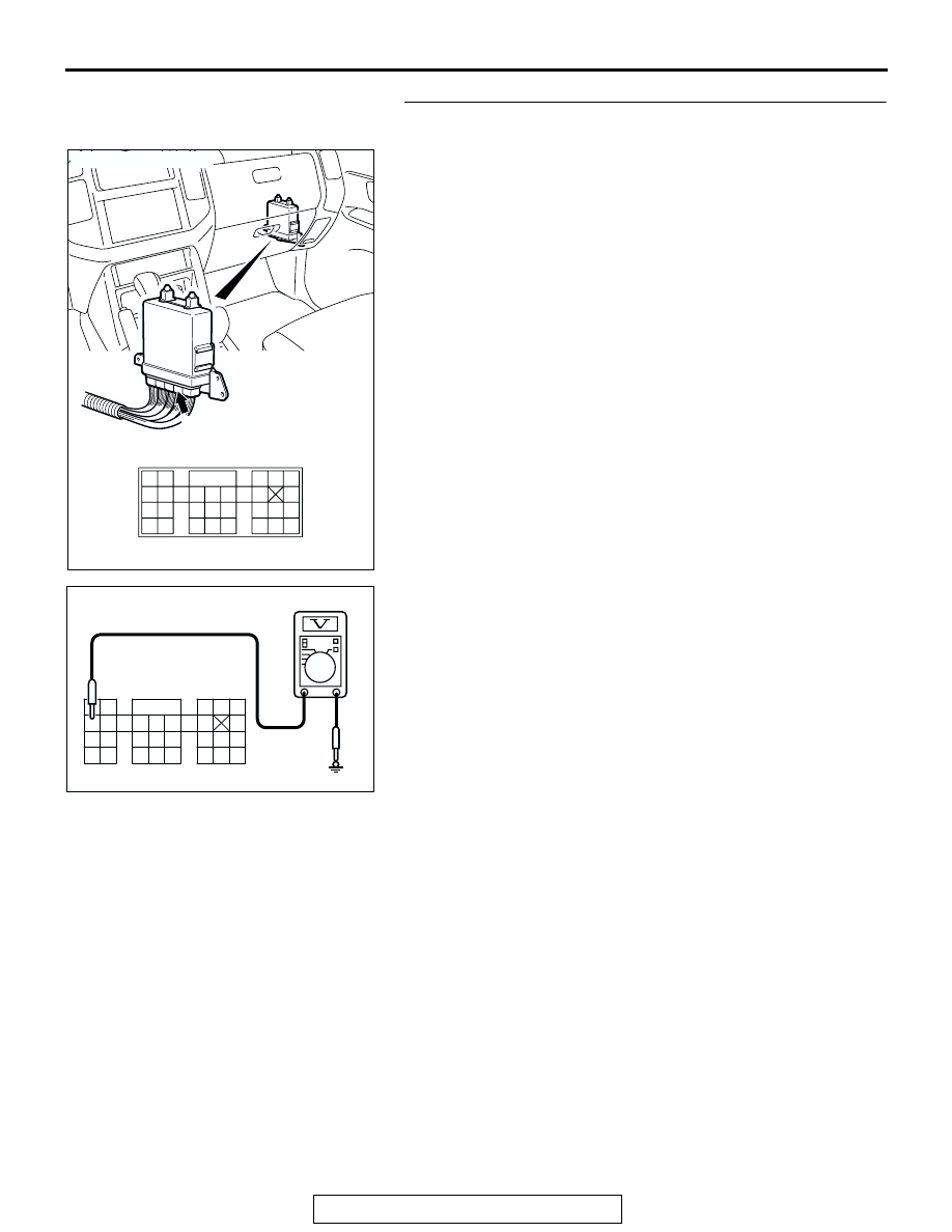
STEP 14. Measure the ground voltage at PCM connector D-
135 by backprobing.
(1) Do not disconnect connector D-135.
(2) Turn the ignition switch to the "ON" position.

(3) Measure the voltage between terminal 96 and ground by 

backprobing.

• Voltage should measure 0.5 volt or less.

(4) Turn the ignition switch to the "LOCK" (OFF) position.
Q: Is the measured voltage within the specified range?

YES : Go to Step 15.
NO :  Go to Step 17.

AC204681AB

CONNECTOR: D-135

D-135 (GR)

91 92

93

101

94 95

96 97 98 99 100

102103

104

105106

107108 109

110 111112

113114

115116 117

118 119120

AC204918 BQ

D-135 HARNESS CONNECTOR : 
HARNESS SIDE

116

97

103

104

112

110 111

106

94 95

98

102

101

100

99

109

115

107

119 120

96

105

91

113

108

117

93

92

114

118

DIAGNOSTIC TROUBLE CODE PROCEDURES <AUTOMATIC TRANSMISSION>

TSB Revision

DIAGNOSTIC TROUBLE CODE PROCEDURES

23Ac-16

STEP 15. Check A/T control solenoid valve assembly 
connector C-03, PCM connector D-135 and intermediate 
connector E-114 for loose, corroded or damaged 
terminals, or terminals pushed back in the connector.
Q: Are the connectors and terminals in good condition?

YES : Go to Step 16.
NO :  Repair or replace the damaged components. Refer to 

GROUP 00E, Harness Connector Inspection 

P.00E-

2

.

AC204395

CONNECTOR : C-03

AE

C-03 (B)

6

10

4

9

5

3

8

2

7

1

AC204681AB

CONNECTOR: D-135

D-135 (GR)

91 92

93

101

94 95

96 97 98 99 100

102103

104

105106

107108 109

110 111112

113114

115116 117

118 119120

AC204176

CONNECTOR : E-114

BD

38

28

16

33

22

10

31

19

7

1

18

30

29

17

5

6

21

20

32

8

2

9

25

13

3

24

23

3435

1112

27

26

3637

14

4

15

DIAGNOSTIC TROUBLE CODE PROCEDURES <AUTOMATIC TRANSMISSION>

TSB Revision

DIAGNOSTIC TROUBLE CODE PROCEDURES

23Ac-17

STEP 16. Check the harness for open circuit or damage 
between A/T control solenoid valve connector C-03 
terminal 2 and PCM connector D-135 terminal 96.
Q: Is the harness wire in good condition?

YES : Go to Step 6.
NO :  Repair or replace the harness wire.

AC204395

CONNECTOR : C-03

AE

C-03 (B)

6

10

4

9

5

3

8

2

7

1

AC204681AB

CONNECTOR: D-135

D-135 (GR)

91 92

93

101

94 95

96 97 98 99 100

102103

104

105106

107108 109

110 111112

113114

115116 117

118 119120

DIAGNOSTIC TROUBLE CODE PROCEDURES <AUTOMATIC TRANSMISSION>

TSB Revision

DIAGNOSTIC TROUBLE CODE PROCEDURES

23Ac-18

STEP 17. Check PCM connector D-135 for loose, corroded 
or damaged terminals, or terminals pushed back in the 
connector.
Q: Are the connector and terminals in good condition?

YES : Go to Step 6.
NO :  Repair or replace the damaged components. Refer to 

GROUP 00E, Harness Connector Inspection 

P.00E-

2

.

DTC 16: Transmission Fluid Temperature Sensor System (Short Circuit)

.

Transmission Fluid Temperature Sensor System 
Circuit
Refer to 

P.23Ac-2

.

.

CIRCUIT OPERATION
Refer to 

P.23Ac-2

.

.

DTC SET CONDITIONS
If the transmission fluid temperature sensor output 
detects the voltage which corresponds to 0 volt for 
more than one second, there is a short in the trans-
mission fluid temperature sensor circuit and DTC 16 
is set.

.

TROUBLESHOOTING HINTS (The most likely 
causes for this code to be set are:)

• Malfunction of the transmission fluid temperature 

sensor circuit

• Damaged harness, connector

• Malfunction of the PCM

AC204681AB

CONNECTOR: D-135

D-135 (GR)

91 92

93

101

94 95

96 97 98 99 100

102103

104

105106

107108 109

110 111112

113114

115116 117

118 119120


Content   ..  881  882  883  884   ..