Mitsubishi Montero (2002-2004). Manual - part 845


  Index      Mitsubishi     Mitsubishi Montero - service repair manual 2002-2004 year


Search            


Content   ..  843  844  845  846   ..


Mitsubishi Montero (2002-2004). Manual - part 845


AUTO-CRUISE CONTROL

TSB Revision

ENGINE AND EMISSION CONTROL

17-43

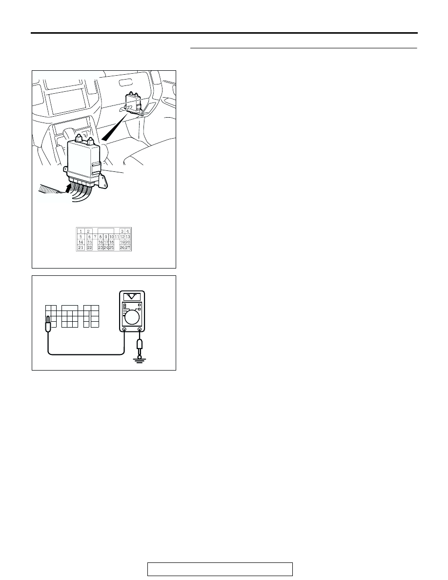
STEP 5. Measure the power supply voltage at PCM 
connector D-132.
(1) Disconnect connector D-132 and measure at the harness 

side.

(2) Turn the ignition switch to the "ON" position.
(3) Switch "ON" the auto-cruise control main switch.

(4) Measure the voltage between terminal 13 and ground.

• The voltage should measure battery positive voltage.

Q: Is the measured voltage battery positive voltage?

YES : Replace the PCM. Refer to 

P.17-54

, Auto-cruise 

Control.

NO :  Go to Step 6.

AC205048

CONNECTOR: D-132

D-132(GR)

PCM

AB

1

2

5

6

8 7

14

15

16

21

22

23

9

17
24

10
18
25

12 11
19
26

13

3

4

20
27

AC205058AB

D-132 HARNESS
CONNECTOR: 
COMPONENT SIDE

AUTO-CRUISE CONTROL

TSB Revision

ENGINE AND EMISSION CONTROL

17-44

STEP 6. Check PCM connector D-132, intermediate 
connector E-110 and combination meter connector D-04 
for looser, corroded or damaged terminals, or terminals 
pushed back in the connector.
Q: Are the connectors and terminals in good condition?

YES : Go to Step 7.
NO :  Repair or replace the damaged components. Refer to 

GROUP 00E, Harness Connector Inspection 

P.00E-

2

.

AC205048

CONNECTOR: D-132

D-132(GR)

PCM

AB

AC205045

6

1

7

2

9

8

10

3

5

12

11

4

1314

E-110

CONNECTOR: E-110

AB

AC205052

CONNECTOR: D-04

AB

D-04 (GR)

AUTO-CRUISE CONTROL

TSB Revision

ENGINE AND EMISSION CONTROL

17-45

STEP 7. Check the harness for open circuit or short circuit 
to ground between PCM connector D-132 terminal 13 and 
combination meter connector D-04 terminal 45.
Q: Is the harness wire in good condition?

YES : Go to Step 8.
NO :  Repair or replace the harness wire.

AC205048

CONNECTOR: D-132

D-132(GR)

PCM

AB

AC205052

CONNECTOR: D-04

AB

D-04 (GR)

AUTO-CRUISE CONTROL

TSB Revision

ENGINE AND EMISSION CONTROL

17-46

STEP 8. Check the combination meter.
(1) Remove the combination meter and measure at the 

combination meter side. (Refer to GROUP 54A, 
Combination Meter Assembly and Vehicle Speed Sensor 

P.54A-65

.)

(2) Measure the continuity between combination meter 

connector D-03 terminal 62 and combination meter 
connector D-04 terminal 45.

• The resistance should measure less than 2 ohms.

Q: Is the resistance less than 2 ohms?

YES : Replace the PCM. Refer to 

P.17-54

, Auto-cruise 

Control.

NO :  Replace the combination meter. Refer to GROUP 

54A, Combination Meter Assembly and Vehicle 
Speed Sensor 

P.54A-65

.

DATA LIST REFERENCE TABLE

M1172002400244

CAUTION

• When shifting the selector lever to D range, the brakes should be applied so that the vehicle does 

not move forward.

• Driving tests always need two persons: one driver and one observer.

NOTE: *:Disconnect the throttle position sensor connector, and then delete the diagnostic trouble code that 
was recorded during the inspection with the use of the MB991502 scan tool after the inspection has been 
completed.

31 32 33 34 35 36 37 38

39

40 41 42 43 44 45 46 47

5152 53 54 55 56 57 58

59

60 6162 63 64 65 66 67

ACX01926

D-04

COMBINATION METER
(REAR VIEW)

AC

CONNECTORS: D-03, D-04 

D-03

MUT-II SCAN 
TOOL 
DISPLAY

ITEM 
NO.

INSPECTION ITEM

INSPECTION REQUIREMENT

NORMAL 
CONDITION

APP SNS 
(MAIN)

12

Accelerator pedal 
position sensor (main)

Ignition 
switch: 
"ON"

Accelerator pedal: Released

905 

− 1,165 mV

Accelerator pedal: Gradually 
depressed

Increases in 
response to the 
pedal depression 
stroke

Accelerator pedal: Fully 
depressed

4,035 mV or more

BRAKE SW

06

Stoplight switch

Brake pedal: Depressed

ON

Brake pedal: Released

OFF


Content   ..  843  844  845  846   ..