Mitsubishi Montero (2002-2004). Manual - part 841
AUTO-CRUISE CONTROL
TSB Revision
ENGINE AND EMISSION CONTROL
17-27
STEP 2. Using scan tool MB991502, read the diagnostic
trouble code.
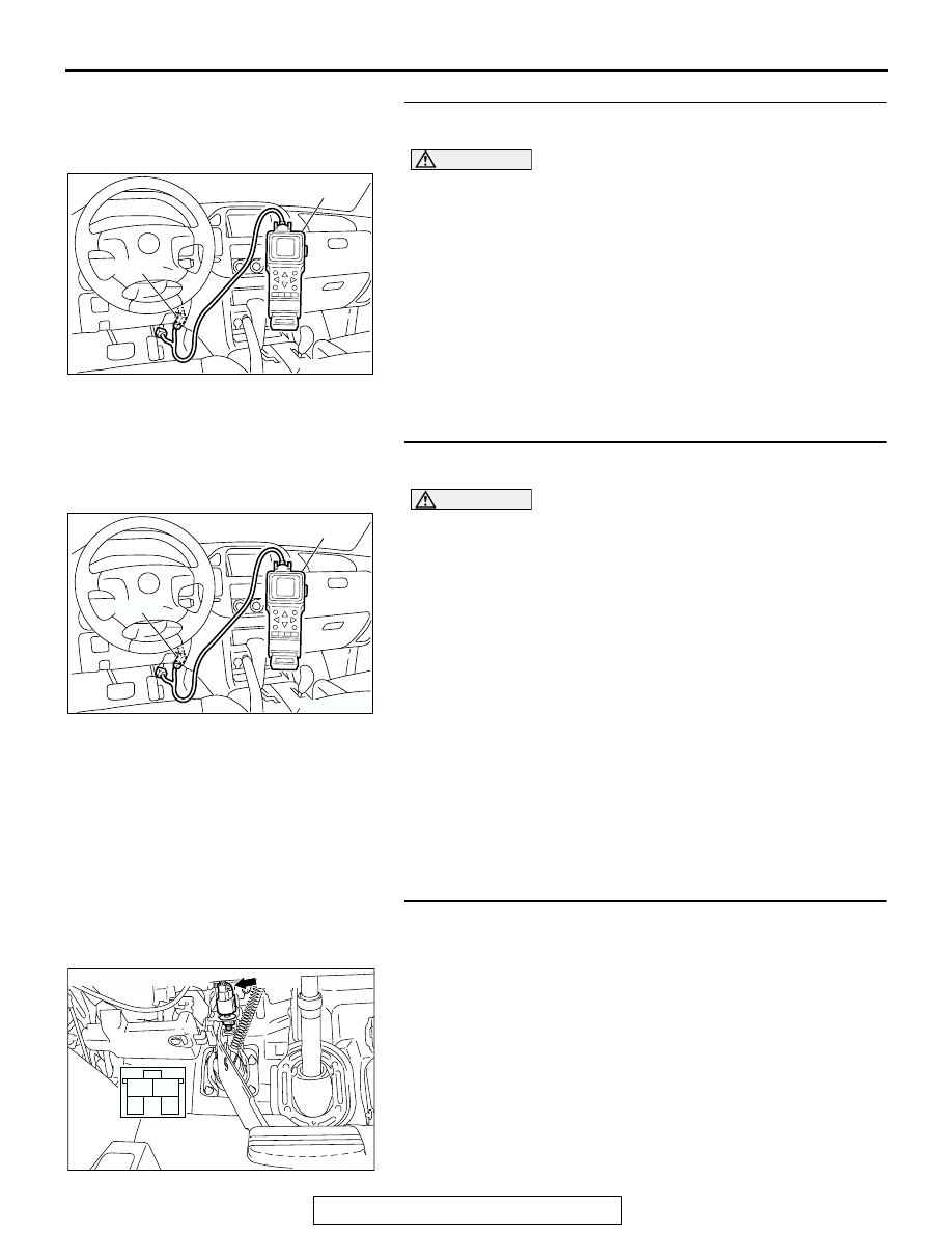
CAUTION
To prevent damage to scan tool MB991502, always turn the
ignition switch to the "LOCK" (OFF) position before con-
necting or disconnecting scan tool MB991502.
(1) Connect scan tool MB991502 to the data link connector.
(2) Turn the ignition switch to the "ON" position.
(3) Check for A/T system diagnostic trouble code.
(4) Turn the ignition switch to the "LOCK" (OFF) position.
Q: Is DTC 26 set?
YES : Refer to GROUP 23A, Diagnostic Trouble Code
Procedures
− DTC 26: Stoplight Switch System
.
NO : Go to Step 3.
STEP 3. Using scan tool MB991502, check data list item 06:
Stoplight Switch.
CAUTION
To prevent damage to scan tool MB991502, always turn the
ignition switch to the "LOCK" (OFF) position before con-
necting or disconnecting scan tool MB991502.
(1) Connect scan tool MB991502 to the data link connector.
(2) Turn the ignition switch to the "ON" position.
(3) Set scan tool MB991502 to data reading mode for auto-
cruise control system item 06, Stoplight Switch.
• When the brake pedal is depressed, the display on scan
tool MB991502 should be "ON."
• When the brake pedal is not depressed, the display on
scan tool MB991502 should be "OFF."
(4) Turn the ignition switch to the "LOCK" (OFF) position.
Q: Is the switch operating properly?
YES : It can be assumed that this malfunction is intermittent.
Refer to GROUP 00, How to Use Troubleshooting/
Inspection Service Points
− How to Cope with
Intermittent Malfunction
NO : Go to Step 4.
STEP 4. Check stoplight switch connector D-123 for
looser, corroded or damaged terminals, or terminals
pushed back in the connector.
Q: Are the connector and terminals in good condition?
YES : Go to Step 5.
NO : Repair or replace the damaged components. Refer to
GROUP 00E, Harness Connector Inspection
ACX02258AC
MB991502
16-PIN
ACX02258AC
MB991502
16-PIN
1
2
3
4
AC204682AB
CONNECTOR: D-123
D-123