Mitsubishi Montero (2002-2004). Manual - part 838


  Index      Mitsubishi     Mitsubishi Montero - service repair manual 2002-2004 year


Search            


Content   ..  836  837  838  839   ..


Mitsubishi Montero (2002-2004). Manual - part 838


AUTO-CRUISE CONTROL

TSB Revision

ENGINE AND EMISSION CONTROL

17-15

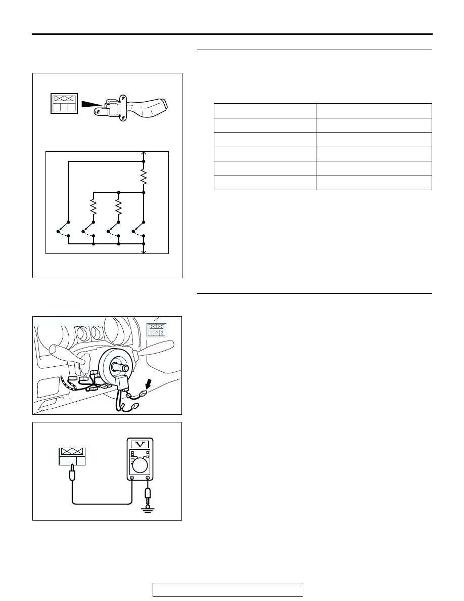
STEP 3. Check the auto-cruise control switch.
(1) Disconnect auto-cruise control switch 

P.17-54

.

(2) Measure the resistance between terminal 2 and terminal 3 

when each of the "SET", "RESUME", "CANCEL" and MAIN 
switch is pressed.

Q: Is the resistance within specifications?

YES : Go to Step 4.
NO :  Replace the auto-cruise control switch. Refer to 

P.17-

54

, Auto-cruise Control.

STEP 4. Measure the auto-cruise control switch power 
supply voltage at connector D-227 by backprobing.
(1) Do not disconnect connector D-227.
(2) Turn the ignition switch to the "ON" position.

(3) Measure the voltage between terminal 2 and ground by 

backprobing.

• When "SET" switch is at the ON position, voltage should 

measure between 2.1 and 2.7 volts.

• When "RESUME" switch is at the ON position, voltage 

should measure between 3.3 and 4.0 volts.

Q: Is the measured voltage within specifications?

YES : Go to Step 5.
NO :   Go to step 6.

SWITCH POSITION

SPECIFIED CONDITION

MAIN switch "OFF"

Open circuit

MAIN switch "ON"

Less than 2 ohms

"CANCEL" switch ON

Approximately 100 

"RESUME" switch ON

Approximately 887 

"SET" switch ON

Approximately 300 

1 2 3

AC203822AB

OFF

OFF

OFF

OFF

ON

ON

ON

ON

CAN

MAIN

RES

SET

2

3

AC205038AB

D-227

CONNECTOR: D-227

1 2 3

AC205053AB

D-227 HARNESS 
CONNECTOR:
HARNESS SIDE

AUTO-CRUISE CONTROL

TSB Revision

ENGINE AND EMISSION CONTROL

17-16

STEP 5. Using scan tool MB991502, check data list item 02: 
Set Switch, item 03: Resume Switch.

CAUTION

To prevent damage to scan tool MB991502, always turn the 
ignition switch to the "LOCK" (OFF) position before con-
necting or disconnecting scan tool MB991502. 
(1) Connect scan tool MB991502 to the data link connector.
(2) Turn the ignition switch to the "ON" position.
(3) Set scan tool MB991502 to data reading mode for auto-

cruise control system item 02, Set Switch.

• When "SET" switch is at the ON position, the display on 

scan tool MB991502 should be "ON."

• When "SET" switch is at the OFF position, the display 

on scan tool MB991502 should be "OFF."

(4) Set scan tool MB991502 to data reading mode for auto-

cruise control system item 03, Resume Switch.

• When "RESUME" switch is at the ON position, the dis-

play on scan tool MB991502 should be "ON."

• When "RESUME" switch is at the OFF position, the dis-

play on scan tool MB991502 should be "OFF."

(5) Turn the ignition switch to the "LOCK" (OFF) position.
Q: Is the switch operating properly?

YES : It can be assumed that this malfunction is intermittent. 

Refer to GROUP 00, How to Use Troubleshooting/
Inspection Service Points 

− How to Cope with 

Intermittent Malfunction 

P.00-6

.

NO :  Replace the PCM. Refer to 

P.17-54

, Auto-cruise 

Control.

ACX02258AC

MB991502

16-PIN

AUTO-CRUISE CONTROL

TSB Revision

ENGINE AND EMISSION CONTROL

17-17

STEP 6. Check auto-cruise control switch connector D-
227, intermediate connector D-230, clock spring connector 
D-226, clock spring connector D-205, intermediate 
connector E-110 and PCM connector D-135 for looser, 
corroded or damaged terminals, or terminals pushed back 
in the connector.

1 2 3

5

4

6

AC205037

2

1

3

CONNECTORS: D-205, D-226, D-227, D-230

D-227

D-226

D-205(B)

D-227

D-226

D-205

D-230(B)

D-230

AB

AC205045

6

1

7

2

9

8

10

3

5

12

11

4

1314

E-110

CONNECTOR: E-110

AB

AUTO-CRUISE CONTROL

TSB Revision

ENGINE AND EMISSION CONTROL

17-18

Q: Are the connectors and terminals in good condition?

YES : Go to Step 7.
NO :  Repair or replace the damaged components. Refer to 

GROUP 00E, Harness Connector Inspection 

P.00E-

2

.

STEP 7. Check the clock spring.
Refer to GROUP 52B, Air Bag Modules and Clock Spring 

P.52Ba-40

.

Q: Is the clock spring operating properly?

YES : Go to Step 8.
NO :  Replace the clock spring. Refer to GROUP 52B, Air 

Bag Modules and Clock Spring 

P.52Ba-33

.

AC205039

CONNECTOR: D-135

D-135(GR)

PCM

AB


Content   ..  836  837  838  839   ..