Mitsubishi Montero (2002-2004). Manual - part 823


  Index      Mitsubishi     Mitsubishi Montero - service repair manual 2002-2004 year


Search            


Content   ..  821  822  823  824   ..


Mitsubishi Montero (2002-2004). Manual - part 823


SRS AIR BAG DIAGNOSIS

TSB Revision

SUPPLEMENTAL RESTRAINT SYSTEM (SRS) DIAGNOSIS

52Bb-161

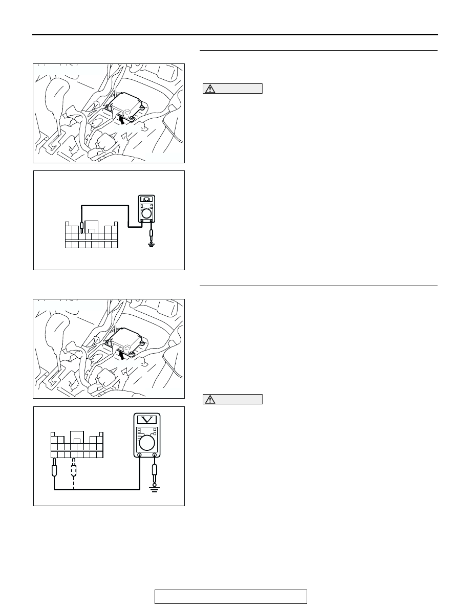
STEP 3. Check the ground circuit to the SRS-ECU.
(1) Disconnect SRS-ECU connector E-08, and measure at the 

wiring harness side.

CAUTION

Do not insert a test probe into the terminal from its front 
side directly as the connector contact pressure may be 
weakened.

(2) Check for continuity between E-08 harness terminal 7 and 

body ground.
It should be less than 2 ohms.

Q: Does continuity exist?

YES : Go to Step 4.
NO :  Go to Step 6.

STEP 4. Check the power supply circuit to the SRS-ECU.
(1) Disconnect SRS-ECU connector E-08, and measure at the 

wiring harness side.

(2) Connect the negative battery terminal.
(3) Turn the ignition switch to the "ON" position.

CAUTION

Do not insert a test probe into the terminal from its front 
side directly as the connector contact pressure may be 
weakened.
(4) Measure the voltage between terminals 13, 16 and body 

ground.
Voltage should measure 9 volts or more.

Q: Is the measured voltage within the specified range?

YES : Recheck the trouble symptom. If it is not solved, 

replace the SRS-ECU. (Refer to 

P.52Ba-31

.) Then go 

to Step 8.

NO :  Go to Step 7.

ACX01478 AG

CONNECTOR: E-08

E-08 (Y)

AC201527

9 10 11 12

13 1415 16

1 2

3 4

5 6 7 8

17 18 19 20

E-08 HARNESS CONNECTOR: 
HARNESS SIDE

AE

ACX01478 AG

CONNECTOR: E-08

E-08 (Y)

AC006265

13 14 15 16 17 18 19 20

5 6 7 8 9 10 11 12

1 2

3 4

AH

E-08 HARNESS
CONNECTOR:
HARNESS SIDE

SRS AIR BAG DIAGNOSIS

TSB Revision

SUPPLEMENTAL RESTRAINT SYSTEM (SRS) DIAGNOSIS

52Bb-162

STEP 5. Check the harness wires between SRS-ECU 
connector E-08 (terminal No.20) and data link connector D-
118 (terminal No.7).
NOTE: After inspecting intermediate connector D-29 inspect 
the wiring harness. If the intermediate connector D-29 is dam-
aged, repair or replace it. (Refer to GROUP 00E, Harness Con-
nector Inspection 

P.00E-2

.). Then go to Step 8.

Q: Are the harness wires between SRS-ECU connector E-

08 (terminal No.20) and data link connector D-118 
(terminal No.7) in good condition?
YES : 
Go to step 8.
NO :  Repair the harness wires between SRS-ECU 

connector E-08 and data link connector D-118. Then 
go to Step 8.

AC204231AF

CONNECTOR : D-29

D-29

D-29

33

22

11

28

17

16

15

14

13

12

25

23 24

26 27

3

1 2

4 5

21

20

19

18
29 30

32

31

7

6

8

10

9

ACX01478AH

CONNECTOR: E-08

E-08 (Y)

HARNESS
CONNECTOR:
HARNESS SIDE

AC204695

CONNECTOR : D-118

AC

D-118 (B)

ACCELLATOR PEDAL

1 2 3 4 5 6 7 8
9 10 11121314 15 16

D-118 
CONNECTOR
(FRONT VIEW)

SRS AIR BAG DIAGNOSIS

TSB Revision

SUPPLEMENTAL RESTRAINT SYSTEM (SRS) DIAGNOSIS

52Bb-163

STEP 6. Check the harness wire between SRS-ECU 
connector E-08 (terminal No.7) and ground.
Q: Is the harness wire between SRS-ECU connector E-08 

(terminal No.7) and ground in good condition?
YES : 
Go to Step 8.
NO :  Repair the harness wire between SRS-ECU 

connector E-08 and ground. Then go to Step 8.

STEP 7. Check the harness wires between SRS-ECU 
connector E-08 (terminal No.13 and 16) and ignition switch 
connector D-204 (terminal No.2).
NOTE: After inspecting junction block connector D-210, D-209 
and D-208 inspect the wiring harness. If the junction block con-
nector D-210, D-209 or D-208 is damaged, repair or replace it. 
(Refer to GROUP 00E, Harness Connector Inspection 

P.00E-

2

.) Then go to Step 8 .

ACX01478AH

CONNECTOR: E-08

E-08 (Y)

HARNESS
CONNECTOR:
HARNESS SIDE

ACX01508

GROUND

AE

AC204257

CONNECTORS : D-208, D-209, D-210

AG

D-210

D-210 HARNESS CONNECTOR:
COMPONENT SIDE

JUNCTION BLOCK
(FRONT VIEW)

5 4

3 2

12

13

10

11

7

8

1

6

9

D-209

D-208

D-209 HARNESS CONNECTOR:
COMPONENT SIDE

D-208 HARNESS CONNECTOR:
COMPONENT SIDE

1

2

3

5

6

4

5 4 3

2

12

13

10

11

7

8

1

6

9

SRS AIR BAG DIAGNOSIS

TSB Revision

SUPPLEMENTAL RESTRAINT SYSTEM (SRS) DIAGNOSIS

52Bb-164

Q: Are the harness wires between SRS-ECU connector E-

08 (terminal No.13 and 16) and ignition switch 
connector D-204 (terminal No.2) in good condition?
YES : 
Go to Step 8.
NO :  Repair the harness wires between SRS-ECU 

connector E-08 and ignition switch connector D-204. 
Then go to Step 8.

STEP 8. Retest the system.
Q: Does the scan tool communicate normally with the SRS 

system?
YES : 
The procedure is complete. (If no malfunctions are 

not found in all steps, an intermittent malfunction is 
suspected. Refer to GROUP 00, How to Use 
Troubleshooting/Inspection Service Points 

− How to 

Cope with Intermittent Malfunction 

P.00-6

.)

NO :  There is no action to be taken.

ACX01478 AD

CONNECTOR: E-08

AC204226AE

CLOCK SPRING

CONNECTOR: D-204

D-204

HARNESS 
CONNECTOR:
COMPONENT 
SIDE

2
5

6

3

4

1


Content   ..  821  822  823  824   ..