Mitsubishi Montero (2002-2004). Manual - part 771
GENERAL DESCRIPTION
TSB Revision
SUPPLEMENTAL RESTRAINT SYSTEM (SRS)
52Ba-17
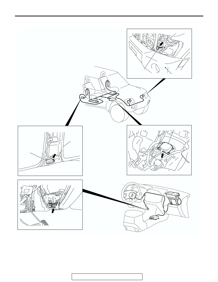
COMPONENT LOCATION
NOTE: The illustration above shows the front impact sensor (LH) and the side impact sensor (RH). The posi-
tion of the front impact sensor (RH) and the side impact sensor (LH) is symmetrical to this.
AC204302
SIDE IMPACT SENSOR
SRS-ECU
DATA LINK CONNECTOR
CENTER
PILLAR
SIDE IMPACT
SENSOR
SRS-ECU
AB
DATA LINK
CONNECTOR
FRONT IMPACT SENSOR
FRONT
IMPACT
SENSOR
FRONT BUMPER