Mitsubishi Montero (2002-2004). Manual - part 763


  Index      Mitsubishi     Mitsubishi Montero - service repair manual 2002-2004 year


Search            


Content   ..  761  762  763  764   ..


Mitsubishi Montero (2002-2004). Manual - part 763


TSB Revision

SYMPTOM PROCEDURES

13Ad-101

.

TROUBLESHOOTING HINTS (The most likely 
causes for this case: )

• Malfunction of the ignition coil.

• Malfunction of the ignition power transistor.

• Improper connector contact, open circuit or short-

circuited harness wire.

• Malfunction of the PCM.

DIAGNOSIS

STEP 1. Check the ignition coil.
Refer to GROUP 16, Ignition System 

− On-vehicle service − 

Ignition Coil Check 

P.16-29

.

Q: Are there any abnormalities?

YES : Go to Step 2.
NO :  Replace the ignition coil. Then confirm that the 

malfunction symptom is eliminated.

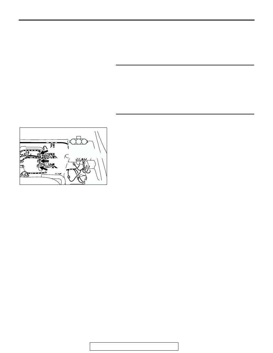
STEP 2. Check harness connectors B-31, B-32, B-34 at 
ignition coil for damage.
Q: Is the harness connector in good condition?

YES : Go to Step 3.
NO :  Repair or replace it. Refer to GROUP 00E, Harness 

Connector Inspection 

P.00E-2

. Then confirm that the 

malfunction symptom is eliminated.

AK201291

1

2

3

B-31(GR)

B-32(GR)

B-34(GR)

AB

CONNECTORS: B-31, B-32, B-34

HARNESS 
CONNECTOR: 
COMPONENT SIDE

TSB Revision

SYMPTOM PROCEDURES

13Ad-102

STEP 3. Measure the power supply voltage at ignition coil 
connectors B-31, B-32, B-34.
(1) Disconnect the connector B-31, B-32, B-34 and measure at 

the harness side.

(2) Turn the ignition switch to the "ON" position.

(3) Measure the voltage between terminal No. 1 and ground.

• Voltage should measure battery positive voltage.

(4) Turn the ignition switch to the "LOCK" (OFF) position.
Q: Is battery positive voltage (approximately 12 volts) 

present?
YES : 
Go to Step 4.
NO :  Check the connectors D-208, D-221, E-111 at 

intermediate connectors for damage, and repair or 
replace as required. Refer to GROUP 00E, Harness 
Connector Inspection 

P.00E-2

. If intermediate 

connector are in good condition, repair harness wire 
between ignition switch connector D-204 (terminal 
No. 2) and ignition coil connector B-31, B-32, B-34 
(terminal No. 1) because of open circuit. Then confirm 
that the malfunction symptom is eliminated.

STEP 4. Check the circuit at ignition coil harness side 
connectors B-31, B-32, B-34.
(1) Disconnect the connectors B-31, B-32, B-34 and measure 

at the harness side.

(2) Engine cranking.

(3) Measure the voltage between terminal No. 3 and ground.

• Voltage should measure 0.3 and 3.0 volts.

(4) Turn the ignition switch to the "LOCK" (OFF) position.
Q: Is the measured voltage between 0.3 and 3.0 volts?

YES : Go to Step 7.
NO :  Go to Step 5.

AK201291

1

2

3

B-31(GR)

B-32(GR)

B-34(GR)

AB

CONNECTORS: B-31, B-32, B-34

HARNESS 
CONNECTOR: 
COMPONENT SIDE

AK000414AI

B-31, B-32, B-34 HERNESS 
CONNECTORS: 
COMPONENT SIDE

1

2

3

AK201291

1

2

3

B-31(GR)

B-32(GR)

B-34(GR)

AB

CONNECTORS: B-31, B-32, B-34

HARNESS 
CONNECTOR: 
COMPONENT SIDE

AK000415 AJ

B-31, B-32, B-34 HERNESS 
CONNECTORS: 
COMPONENT SIDE

1

2

3

TSB Revision

SYMPTOM PROCEDURES

13Ad-103

STEP 5. Check connector D-133 at PCM for damage.
Q: Is the connector in good condition?

YES : Go to Step 6.
NO :  Repair or replace it. Refer to GROUP 00E, Harness 

Connector Inspection 

P.00E-2

. Then confirm that the 

malfunction symptom is eliminated.

STEP 6. Check for open circuit and short circuit to ground 
between ignition coil connector and PCM connector.

a. Check the harness wire between ignition coil connector B-

32 (terminal No. 3) and PCM connector D-133 (terminal No. 
31) when checking ignition coil 1.

b. Check the harness wire between ignition coil connector B-

34 (terminal No. 3) and PCM connector D-133 (terminal No. 
35) when checking ignition coil 2.

c. Check the harness wire between ignition coil connector B-

31 (terminal No. 3) and PCM connector D-133 (terminal No. 
44) when checking ignition coil 3.

Q: Is the harness wire in good condition?

YES : Replace the PCM. Then confirm that the malfunction 

symptom is eliminated.

NO :  Repair it. Then confirm that the malfunction symptom 

is eliminated.

AK200939

31

32

33

34

35

36

37

38

39

40

41

42

43

44

45

46

47

48

49

52

53

54

55

56

57

58

50

51

AB

CONNECTOR: D-133

HARNESS CONNECTOR: 
COMPONENT SIDE

PCM

D-133(GR)

AK201291

1

2

3

B-31(GR)

B-32(GR)

B-34(GR)

AB

CONNECTORS: B-31, B-32, B-34

HARNESS 
CONNECTOR: 
COMPONENT SIDE

AK200939

31

32

33

34

35

36

37

38

39

40

41

42

43

44

45

46

47

48

49

52

53

54

55

56

57

58

50

51

AB

CONNECTOR: D-133

HARNESS CONNECTOR: 
COMPONENT SIDE

PCM

D-133(GR)

TSB Revision

SYMPTOM PROCEDURES

13Ad-104

STEP 7. Check for harness damage between ignition coil 
connector and PCM connector.

a. Check the harness wire between ignition coil connector B-

32 (terminal No. 3) and PCM connector D-133 (terminal No. 
31) when checking ignition coil 1.

b. Check the harness wire between ignition coil connector B-

34 (terminal No. 3) and PCM connector D-133 (terminal No. 
35) when checking ignition coil 2.

c. Check the harness wire between ignition coil connector B-

31 (terminal No. 3) and PCM connector D-133 (terminal No. 
44) when checking ignition coil 3.

Q: Is the harness wire in good condition?

YES : Go to Step 8.
NO :  Repair it. Then confirm that the malfunction symptom 

is eliminated.

STEP 8. Check for continuity at ignition coil harness side 
connectors B-31, B-32, B-34.
(1) Disconnect the connectors B-31, B-32, B-34 and measure 

at the harness side.

(2) Check for continuity between terminal No. 2 and ground.

• Should be less than 2 ohms.

Q: Does continuity exist?

YES : Go to Step 9.
NO :  Repair harness wire between ignition coil connectors 

B-31, B-32, B-34 (terminal No. 2) and ground 
because of open circuit or harness damage. Then 
confirm that the malfunction symptom is eliminated.

AK201291

1

2

3

B-31(GR)

B-32(GR)

B-34(GR)

AB

CONNECTORS: B-31, B-32, B-34

HARNESS 
CONNECTOR: 
COMPONENT SIDE

AK200939

31

32

33

34

35

36

37

38

39

40

41

42

43

44

45

46

47

48

49

52

53

54

55

56

57

58

50

51

AB

CONNECTOR: D-133

HARNESS CONNECTOR: 
COMPONENT SIDE

PCM

D-133(GR)

AK201291

1

2

3

B-31(GR)

B-32(GR)

B-34(GR)

AB

CONNECTORS: B-31, B-32, B-34

HARNESS 
CONNECTOR: 
COMPONENT SIDE

AK101265

1

2

3

AI

B-31, B-32, B-34 HERNESS 
CONNECTORS: 
COMPONENT SIDE

1

2

3


Content   ..  761  762  763  764   ..