Mitsubishi Montero (2002-2004). Manual - part 751
TSB Revision
SYMPTOM PROCEDURES
13Ad-53
INSPECTION PROCEDURE 17: Deceleration Shock
.
COMMENT
• There may be a sudden change in air flow
through the throttle valve, causing the vehicle to
decelerate rapidly for an instant.
.
TROUBLESHOOTING HINTS (The most likely
causes for this case: )
• Malfunction of the electronic control throttle valve
system.
DIAGNOSIS
Required Special Tool:
• MB991502: Scan Tool (MUT-II)
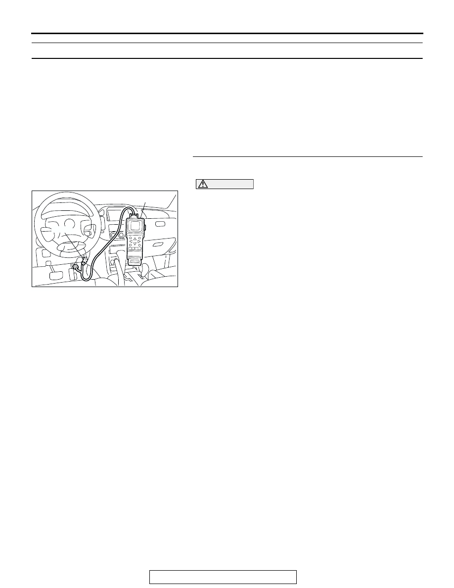
STEP 1. Using scan tool MB991502, read the diagnostic
trouble code (DTC).
CAUTION
To prevent damage to scan tool MB991502, always turn the
ignition switch to the "LOCK" (OFF) position before con-
necting or disconnecting scan tool MB991502.
(1) Connect scan tool MB991502 to the data link connector.
(2) Turn the ignition switch to the "ON" position.
(3) Read the DTC.
(4) Turn the ignition switch to the "LOCK" (OFF) position.
Q: Is DTC set?
YES : Refer to GROUP 13A, Diagnostic Trouble Code Chart
NO : Refer to GROUP 13A, On-vehicle Service
− Clean the
throttle valve area.
ACX01539
16-PIN
MB991502
AC