Mitsubishi Montero (2002-2004). Manual - part 736


  Index      Mitsubishi     Mitsubishi Montero - service repair manual 2002-2004 year


Search            


Content   ..  734  735  736  737   ..


Mitsubishi Montero (2002-2004). Manual - part 736


TSB Revision

DIAGNOSTIC TROUBLE CODE PROCEDURES

13Ac-641

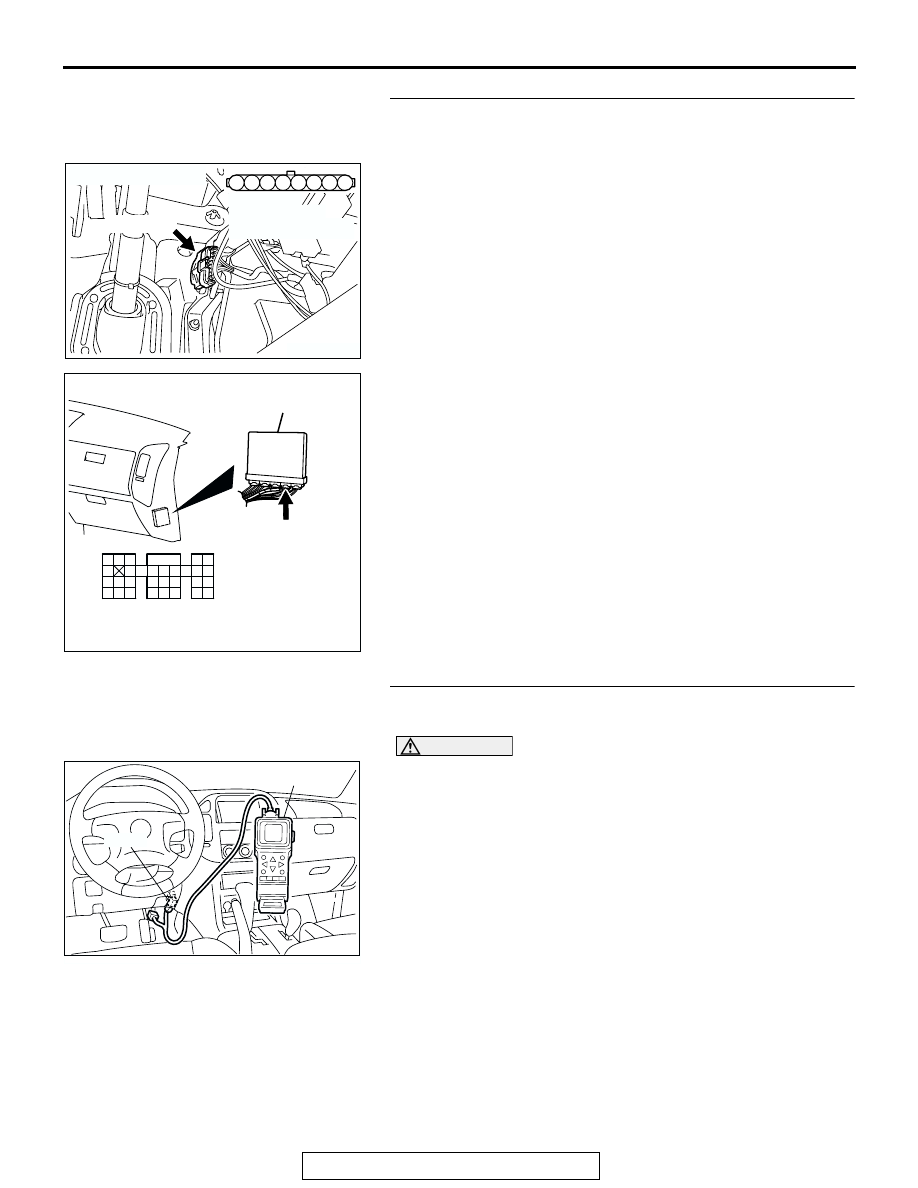
STEP 5. Check for harness damage between accelerator 
pedal position sensor connector D-138 (terminal No. 1) and 
PCM connector D-135 (terminal No. 91).
Q: Is the harness wire in good condition?

YES : Go to Step 6.
NO :  Repair it. Then go to Step 17.

STEP 6. Using scan tool MB991502, read the diagnostic 
trouble code (DTC).

CAUTION

To prevent damage to scan tool MB991502, always turn the 
ignition switch to the "LOCK"(OFF) position before con-
necting or disconnecting scan tool MB991502.
(1) Connect scan tool MB991502 to the data link connector.
(2) Turn the ignition switch to the "ON" position.
(3) After the DTC has been deleted, read the DTC again.
(4) Turn the ignition switch to the "LOCK"(OFF) position.
Q: Is DTC P2138 set?

YES : Replace the PCM. Then go to Step 17.
NO :  It can be assumed that this malfunction is intermittent. 

Refer to GROUP 00, How to Use Troubleshooting/
Inspection Service Points 

P.00-6

.

AK200945

3

4

5

1

2

8

6

7

AB

CONNECTOR: D-138

HARNESS 
CONNECTOR: 
COMPONENT SIDE

D-138(GR)

AK200947

91

92

93

94

95

96

97

98

99

100

101

102

103

104

105

106

107

108

109

110

111

112

113

114

115

116

117

118

119

120

CONNECTOR: D-135

HARNESS CONNECTOR: 
COMPONENT SIDE

AB

PCM

D-135(GR)

ACX01539

16-PIN

MB991502

AC

TSB Revision

DIAGNOSTIC TROUBLE CODE PROCEDURES

13Ac-642

STEP 7. Check the continuity at accelerator pedal position 
sensor harness side connector D-138.
(1) Disconnect the connector D-138 and measure at the 

harness side.

(2) Measure the continuity between terminal No. 7 and ground.

• Should be less than 2 ohms.

Q: Is the continuity normal?

YES : Go to Step 11.
NO :  Go to Step 8.

STEP 8. Check connector D-135 at PCM for damage.
Q: Is the connector in good condition?

YES : Go to Step 9.
NO :  Repair or replace it. Refer to GROUP 00E, Harness 

Connector Inspection 

P.00E-2

. Then go to Step 17.

AK200945

3

4

5

1

2

8

6

7

AB

CONNECTOR: D-138

HARNESS 
CONNECTOR: 
COMPONENT SIDE

D-138(GR)

3

4

5

1

2

8

6

7

AK201455

B-138 HARNESS 
CONNECTOR: 
COMPONENT SIDE

AB

AK200947

91

92

93

94

95

96

97

98

99

100

101

102

103

104

105

106

107

108

109

110

111

112

113

114

115

116

117

118

119

120

CONNECTOR: D-135

HARNESS CONNECTOR: 
COMPONENT SIDE

AB

PCM

D-135(GR)

TSB Revision

DIAGNOSTIC TROUBLE CODE PROCEDURES

13Ac-643

STEP 9. Check for harness damage between accelerator 
pedal position sensor connector D-138 (terminal No. 7) and 
PCM connector D-135 (terminal No. 96).
Q: Is the harness wire in good condition?

YES : Go to Step 10.
NO :  Repair it. Then go to Step 17.

STEP 10. Using scan tool MB991502, read the diagnostic 
trouble code (DTC).

CAUTION

To prevent damage to scan tool MB991502, always turn the 
ignition switch to the "LOCK"(OFF) position before con-
necting or disconnecting scan tool MB991502.
(1) Connect scan tool MB991502 to the data link connector.
(2) Turn the ignition switch to the "ON" position.
(3) After the DTC has been deleted, read the DTC again.
(4) Turn the ignition switch to the "LOCK"(OFF) position.
Q: Is DTC P2138 set?

YES : Replace the PCM. Then go to Step 17.
NO :  It can be assumed that this malfunction is intermittent. 

Refer to GROUP 00, How to Use Troubleshooting/
Inspectio Service Points 

P.00-6

.

AK200945

3

4

5

1

2

8

6

7

AB

CONNECTOR: D-138

HARNESS 
CONNECTOR: 
COMPONENT SIDE

D-138(GR)

AK200947

91

92

93

94

95

96

97

98

99

100

101

102

103

104

105

106

107

108

109

110

111

112

113

114

115

116

117

118

119

120

CONNECTOR: D-135

HARNESS CONNECTOR: 
COMPONENT SIDE

AB

PCM

D-135(GR)

ACX01539

16-PIN

MB991502

AC

TSB Revision

DIAGNOSTIC TROUBLE CODE PROCEDURES

13Ac-644

STEP 11. Check connector D-135 at PCM for damage.
Q: Is the connector in good condition?

YES : Go to Step 12.
NO :  Repair or replace it. Refer to GROUP 00E, Harness 

Connector Inspection 

P.00E-2

. Then go to Step 17.

STEP 12. Check for harness damage between accelerator 
pedal position sensor connector D-138 (terminal No. 2) and 
PCM connector D-135 (terminal No. 92).
Q: Is the harness wire in good condition?

YES : Go to Step 13.
NO :  Repair it. Then go to Step 17.

AK200947

91

92

93

94

95

96

97

98

99

100

101

102

103

104

105

106

107

108

109

110

111

112

113

114

115

116

117

118

119

120

CONNECTOR: D-135

HARNESS CONNECTOR: 
COMPONENT SIDE

AB

PCM

D-135(GR)

AK200945

3

4

5

1

2

8

6

7

AB

CONNECTOR: D-138

HARNESS 
CONNECTOR: 
COMPONENT SIDE

D-138(GR)

AK200947

91

92

93

94

95

96

97

98

99

100

101

102

103

104

105

106

107

108

109

110

111

112

113

114

115

116

117

118

119

120

CONNECTOR: D-135

HARNESS CONNECTOR: 
COMPONENT SIDE

AB

PCM

D-135(GR)


Content   ..  734  735  736  737   ..