Mitsubishi Montero (2002-2004). Manual - part 730


  Index      Mitsubishi     Mitsubishi Montero - service repair manual 2002-2004 year


Search            


Content   ..  728  729  730  731   ..


Mitsubishi Montero (2002-2004). Manual - part 730


TSB Revision

DIAGNOSTIC TROUBLE CODE PROCEDURES

13Ac-617

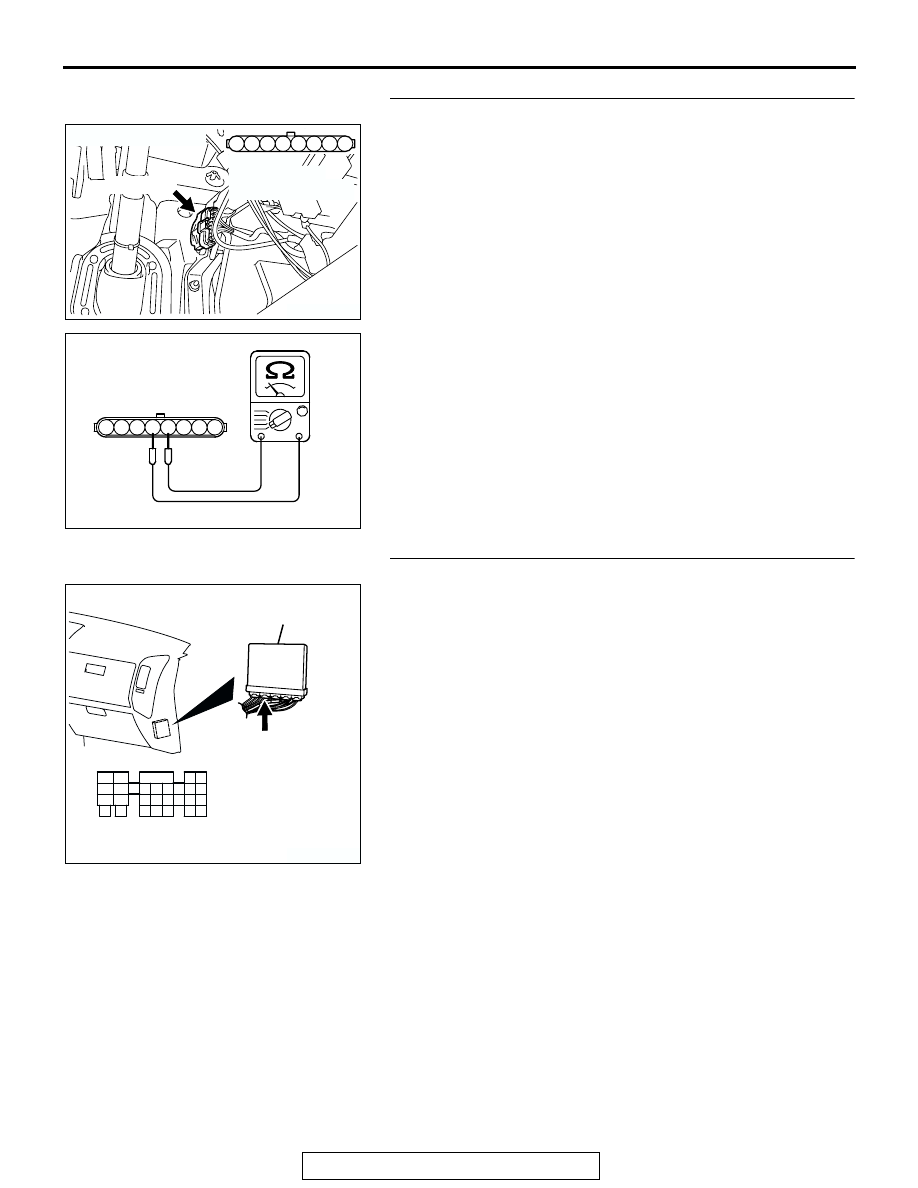
STEP 7. Check the accelerator pedal position switch.
(1) Disconnect the accelerator pedal position switch connector 

D-138.

(2) Check the continuity between accelerator pedal position 

switch side connector terminal No. 4 and No. 5.

 Standard value:

Continuity (foot released from accelerator pedal)         
Non-continuity (accelerator pedal depressed)

Q: Is the switch operating properly?

YES : Go to Step 8.
NO :  Replace the accelerator pedal position sensor. Then 

go to Step 11.

STEP 8. Check connector D-133 at PCM for damage.
Q: Is the connector in good condition?

YES : Go to Step 9.
NO :  Repair or replace it. Refer to GROUP 00E, Harness 

Connector Inspection 

P.00E-2

. Then go to Step 11.

AK200945

3

4

5

1

2

8

6

7

AB

CONNECTOR: D-138

HARNESS 
CONNECTOR: 
COMPONENT SIDE

D-138(GR)

6 7 8

1 2 3 4 5

AK201453AB

ACCELERATOR PEDAL
POSITION SWITCH
SIDE CONNECTOR

AK200939

31

32

33

34

35

36

37

38

39

40

41

42

43

44

45

46

47

48

49

52

53

54

55

56

57

58

50

51

AB

CONNECTOR: D-133

HARNESS CONNECTOR: 
COMPONENT SIDE

PCM

D-133(GR)

TSB Revision

DIAGNOSTIC TROUBLE CODE PROCEDURES

13Ac-618

STEP 9. Check for short circuit to ground between 
accelerator pedal position switch connector D-138 
(terminal No. 4) and PCM connector D-133 (terminal No. 
38).
Q: Is the harness wire in good condition?

YES : Go to Step 10.
NO :  Repair it. Then go to Step 11.

STEP 10. Using scan tool MB991502, read the diagnostic 
trouble code (DTC).

CAUTION

To prevent damage to scan tool MB991502, always turn the 
ignition switch to the "LOCK"(OFF) position before con-
necting or disconnecting scan tool MB991502.
(1) Connect scan tool MB991502 to the data link connector.
(2) Turn the ignition switch to the "ON" position.
(3) After the DTC has been deleted, read the DTC again.
(4) Turn the ignition switch to the "LOCK"(OFF) position.
Q: Is DTC P2126 set?

YES : Replace the PCM.Then go to Step 11.
NO :  It can be assumed that this malfunction is intermittent.      

Refer to GROUP 00, How to Use Troubleshooting/
Inspection Service Points 

P.00-6

.

AK200945

3

4

5

1

2

8

6

7

AB

CONNECTOR: D-138

HARNESS 
CONNECTOR: 
COMPONENT SIDE

D-138(GR)

AK200939

31

32

33

34

35

36

37

38

39

40

41

42

43

44

45

46

47

48

49

52

53

54

55

56

57

58

50

51

AB

CONNECTOR: D-133

HARNESS CONNECTOR: 
COMPONENT SIDE

PCM

D-133(GR)

ACX01539

16-PIN

MB991502

AC

TSB Revision

DIAGNOSTIC TROUBLE CODE PROCEDURES

13Ac-619

STEP 11. Using scan tool MB991502, read the diagnostic 
trouble code (DTC).
(1) Connect scan tool MB991502 to the data link connector.
(2) Turn the ignition switch to the "ON" position.
(3) After the DTC has been deleted, read the DTC again.
(4) Turn the ignition switch to the "LOCK"(OFF) position.
Q: Is DTC P2126 set?

YES : Retry the troubleshooting.
NO :  The inspection is complete.

DTC P2127: Accelerator Pedal Position Sensor (Sub) Circuit Low Input

ACX01539

16-PIN

MB991502

AC

AK201164

GREEN-YELLO

W

GREEN-ORANGE

BLA

CK

5 V

97

8

ACCELERATOR 
PEDAL 

POSITION
SENSOR
(SUB)

POWERTRAIN CONTROL MODULE (PCM)

107

96

6

7

Accelerator Pedal Position Sensor (Sub) Circuit

9192

939495

96979899

100

105

113114

115116117

118119120

106

107108109

110111112

101102103

104

D-135

(MU803805)

D-138 

(MU802073)

6 7 8

1 2 3 4 5

TSB Revision

DIAGNOSTIC TROUBLE CODE PROCEDURES

13Ac-620

.

CIRCUIT OPERATION

• A 5-volt power supply is applied on the APS (sub) 

power terminal (terminal No. 8) from the PCM 
(terminal No. 97).
The ground terminal (terminal No. 7) is grounded 
with PCM (terminal No. 96).

• When the accelerator pedal is moved from the 

idle position to the fully opened position, the 
resister between the APS (sub) output terminal 
(terminal No. 6) and ground terminal will increase 
according to the rotation.

.

TECHNICAL DESCRIPTION

• The APS (sub) outputs voltage which corre-

sponds to the accelerator pedal depression.

• The PCM checks whether the voltage is within a 

specified range.

.

DTC SET CONDITIONS

Check Conditions

• Ignition switch "ON" position.

Judgement Criteria

• APS2 output voltage is 0.2 volts or less for 1 sec-

ond.

.

TROUBLESHOOTING HINTS (The most likely 
causes for this code to be set are:)

• APS failed or maladjusted.

• Open or shorted APS (sub) circuit, or loose con-

nector.

• PCM failed.

AK200944

ACCELERATOR
PEDAL 
POSITION 
SENSOR

AB

D-138(GR)

CONNECTOR: D-138

AK201038AF

CONNECTOR: D-135

PCM

D-135(GR)


Content   ..  728  729  730  731   ..