Mitsubishi Montero (2002-2004). Manual - part 711


  Index      Mitsubishi     Mitsubishi Montero - service repair manual 2002-2004 year


Search            


Content   ..  709  710  711  712   ..


Mitsubishi Montero (2002-2004). Manual - part 711


TSB Revision

DIAGNOSTIC TROUBLE CODE PROCEDURES

13Ac-541

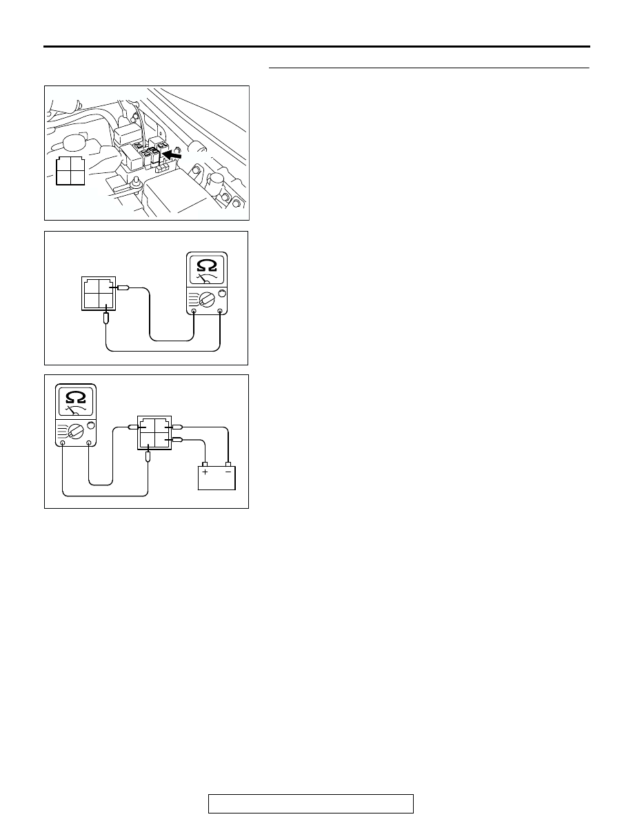
STEP 2. Check the throttle actuator control motor relay.
(1) Remove the throttle actuator control motor relay.

(2) Check for continuity between the throttle actuator control 

motor relay terminal No. 2 and No. 4.

• There should be continuity (approximately 70 ohms).

(3) Use jumper wires to connect throttle actuator control motor 

relay terminal No. 4 to the positive battery terminal and 
terminal No. 2 to the negative battery terminal.

(4) Check the continuity between the throttle actuator control 

motor relay terminal No. 1 and No. 3 while connecting and 
disconnecting the jumper wire at the negative battery 
terminal.

• Should be less than 2 ohms. (Negative battery terminal  

connected.)

• Should be open loop. (Negative battery terminal  discon-

nected.)

(5) Install the throttle actuator control motor relay.
Q: Is the resistance normal?

YES : Go to Step 3.
NO :  Replace the throttle actuator control motor relay.       

Then go to Step 14.

AK201172

2 1

3

4

B-23X

AB

CONNECTOR: B-23X

HARNESS 
CONNECTOR: 
COMPONENT SIDE

1

2

3

4

AK201380AC

THROTTLE ACTUATOR 
CONTROL MOTOR RELAY
SIDE CONNECTOR

1

2

3

4

AK201381

THROTTLE ACTUATOR 
CONTROL MOTOR RELAY
SIDE CONNECTOR

AC

TSB Revision

DIAGNOSTIC TROUBLE CODE PROCEDURES

13Ac-542

STEP 3. Measure the power supply voltage at throttle 
actuator control motor relay harness side connector B-23X
(1) Disconnect the connector B-23X and measure at the 

harness side.

(2) Measure the voltage between terminal No. 3 and ground.

• Voltage should be battery positive voltage.

Q: Is battery positive voltage (approximately 12 volts) 

present?
YES : 
Go to Step 4.
NO :  Check harness connector A-03 at intermediate 

connector for damage, and repair or replace as 
required. Refer to GROUP 00E, Harness Connector 
Inspection 

P.00E-2

. If intermediate connector A-03 is 

in good condition, repair it because of open circuit or 
short circuit to ground between fusible link (5) and 
throttle actuator control motor relay connector B-23X 
(terminal No. 3). Then go to Step 14.

STEP 4. Measure the power supply voltage at throttle 
actuator control motor relay harness side connector B-
23X.
(1) Disconnect the connector B-23X and measure at the 

harness side.

(2) Turn the ignition switch to the "ON" position.

(3) Measure the voltage between terminal No. 4 and ground.

• Voltage should be battery positive voltage.

(4) Turn the ignition switch to the "LOCK"(OFF) position.
Q: Is battery positive voltage (approximately 12 volts) 

present?
YES : 
Go to Step 6.
NO :  Go to Step 5.

AK201172

2 1

3

4

B-23X

AB

CONNECTOR: B-23X

HARNESS 
CONNECTOR: 
COMPONENT SIDE

2 1

3

4

AK201382AC

B-23X HARNESS
CONNECTOR:
COMPONFNT SIDE

AK201172

2 1

3

4

B-23X

AB

CONNECTOR: B-23X

HARNESS 
CONNECTOR: 
COMPONENT SIDE

2 1

3

4

AK201383

B-23X HARNESS
CONNECTOR:
COMPONFNT SIDE

AC

TSB Revision

DIAGNOSTIC TROUBLE CODE PROCEDURES

13Ac-543

STEP 5. Check connector B-22X at MFI relay for damage.
Q: Is the connector in good condition?

YES : Repair harness wire between MFI relay connector B-

22X (terminal No. 1) and throttle actuator control 
motor relay connector B-23X (terminal No. 4) 
because of open circuit or short circuit to ground. 
Then go to Step 14.

NO :  Repair or replace it. Refer to GROUP 00E, Harness 

Connector Inspection 

P.00E-2

. Then go to Step 14.

STEP 6. Measure the power supply voltage at PCM harness 
side connector D-132.
(1) Disconnect the connector D-132 and measure at the 

harness side.

(2) Turn the ignition switch to the "ON" position.

(3) Measure the voltage between terminal No. 15 and ground.

• Voltage should be battery positive voltage.

(4) Turn the ignition switch to the "LOCK"(OFF) position.
Q: Is battery positive voltage (approximately 12 volts) 

present?
YES : 
Go to Step 7.
NO :  Repair harness wire between throttle actuator control 

motor relay connector B-23X (terminal No. 2) and 
PCM connector D-132 (terminal No. 15) because of 
open circuit or short circuit to ground. Then go to Step 
14.

AK200951

2 1

3

4

B-22X

AB

CONNECTOR: B-22X

HARNESS 
CONNECTOR: 
COMPONENT SIDE

AK200938

2

3

4

5

6

7

8

9

1

10

14

15

16

17

18

19

20

21

22

23

24

25

26

27

11

12

13

AB

CONNECTOR: D-132

HARNESS CONNECTOR: 
COMPONENT SIDE

PCM

D-132(GR)

2

3

4

5

6

7

8

9

1

10

14

15

16

17

18

19

20

21

22

23

24

25

26

27

11

12

13

AK201447

D-132 HARNESS 
CONNECTOR: 
COMPONENT SIDE

AB

TSB Revision

DIAGNOSTIC TROUBLE CODE PROCEDURES

13Ac-544

STEP 7. Measure the power supply voltage at PCM harness 
side connector D-136.
(1) Disconnect the connector D-136 and measure at the 

harness side.

(2) Turn the ignition switch to the "ON" position.

(3) Measure the voltage between terminal No. 132 and ground.

• Voltage should be battery positive voltage.

(4) Turn the ignition switch to the "LOCK"(OFF) position.
Q: Is battery positive voltage (approximately 12 volts) 

present?
YES : 
Go to Step 10.
NO :  Go to Step 8.

AK201170

121

122

123

124

125

126

127

128

129

130

131

132

133

134

135

136

137

138

139

140

141

142

143

144

145

146

CONNECTOR: D-136

PCM

D-136(GR)

HARNESS CONNECTOR: 
COMPONENT SIDE

AB

121

122

123

124

125

126

127

128

129

130

131

132

133

134

135

136

137

138

139

140

141

142

143

144

145

146

AK201448

AB

D-136 HARNESS 
CONNECTOR: 
COMPONENT SIDE


Content   ..  709  710  711  712   ..