Mitsubishi Montero (2002-2004). Manual - part 706


  Index      Mitsubishi     Mitsubishi Montero - service repair manual 2002-2004 year


Search            


Content   ..  704  705  706  707   ..


Mitsubishi Montero (2002-2004). Manual - part 706


TSB Revision

DIAGNOSTIC TROUBLE CODE PROCEDURES

13Ac-521

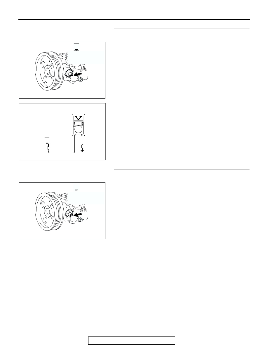
STEP 2. Measure the power supply voltage at power 
steering pressure switch connector B-29 by backprobing. 
(1) Do not disconnect the connector B-29. 
(2) Start the engine and run at idle. 

(3) Measure the voltage between terminal No. 1 and ground by 

backprobing. 

• When steering wheel is stationary, voltage should be 

battery positive voltage. 

• When steering wheel is turned, voltage should be 1 volt 

or less. 

(4) Turn the ignition switch to the "LOCK" (OFF) position. 
Q: Is the voltage normal? 

YES : Go to Step 3. 
NO :  Go to Step 5. 

STEP 3. Check harness connector B-29 at power steering 
pressure switch for damage. 
Q: Is the harness connector in good condition? 

YES : Go to Step 4. 
NO :  Repair or replace it. Refer to GROUP 00E, Harness 

Connector Inspection 

P.00E-2

Then go to Step 14.      

AK200973

1

AB

CONNECTOR: B-29

B-29(B)

HARNESS 
CONNECTOR: 
COMPONENT SIDE

AKX01551

1

AC

B-29 HARNESS 
CONNECTOR: 
HARNESS SIDE

AK200973

1

AB

CONNECTOR: B-29

B-29(B)

HARNESS 
CONNECTOR: 
COMPONENT SIDE

TSB Revision

DIAGNOSTIC TROUBLE CODE PROCEDURES

13Ac-522

STEP 4. Using scan tool MB991502, check data list item 27: 
Power Steering Pressure Switch. 

CAUTION

To prevent damage to scan tool MB991502, always turn the 
ignition switch to the "LOCK" (OFF) position before con-
necting or disconnecting scan tool MB991502. 
(1) Connect scan tool MB991502 to the data link connector. 
(2) Start the engine and run at idle. 
(3) Set scan tool MB991502 to the data reading mode for item 

27, Power Steering Pressure Switch. 

• If the steering wheel is stopped while idling, "OFF" will 

be displayed. 

• If the steering wheel is steered while idling, "ON" will be 

displayed. 

(4) Turn the ignition switch to the "LOCK" (OFF) position. 
Q: Is the switch operating properly? 

YES : It can be assumed that this malfunction is intermittent. 

Refer to GROUP 00, How to Use Troubleshooting/
Inspection Service Points 

P.00-6

.

NO :  Replace the PCM. Then go to Step 14

STEP 5. Check harness connector B-29 at power steering 
pressure switch for damage. 
Q: Is the harness connector in good condition? 

YES : Go to Step 6. 
NO :  Repair or replace it. Refer to GROUP 00E, Harness 

Connector Inspection 

P.00E-2

. Then go to Step 14.    

ACX01539

16-PIN

MB991502

AC

AK200973

1

AB

CONNECTOR: B-29

B-29(B)

HARNESS 
CONNECTOR: 
COMPONENT SIDE

TSB Revision

DIAGNOSTIC TROUBLE CODE PROCEDURES

13Ac-523

STEP 6. Measure the power supply voltage at power 
steering pressure switch harness side connector B-29. 
(1) Disconnect the connector B-29 and measure at the harness 

side. 

(2) Turn the ignition switch to the "ON" position. 

(3) Measure the voltage between terminal No. 1 and ground. 

• Voltage should be battery positive voltage. 

(4) Turn the ignition switch to the "LOCK" (OFF) position. 
Q: Is battery positive voltage (approximately 12 volts) 

present?
YES : 
Go to Step 11. 
NO :  Go to Step 7. 

STEP 7. Measure the power supply voltage at PCM 
connector D-133 by backprobing. 
(1) Do not disconnect the PCM connector D-133. 
(2) Disconnect the power steering pressure switch connector 

B-29. 

(3) Turn the ignition switch to the "ON" position. 

(4) Measure the voltage between terminal No. 47 and ground 

by backprobing. 

• Voltage should be between battery positive voltage. 

(5) Turn the ignition switch to the "LOCK" (OFF) position. 
Q: Is battery positive voltage (approximately 12 volts) 

present?
YES : 
Go to Step 8. 
NO :  Go to Step 9.

AK200973

1

AB

CONNECTOR: B-29

B-29(B)

HARNESS 
CONNECTOR: 
COMPONENT SIDE

AKX01429AC

1

B-29 HARNESS 
CONNECTOR: 
COMPONENT SIDE

AK200939

31

32

33

34

35

36

37

38

39

40

41

42

43

44

45

46

47

48

49

52

53

54

55

56

57

58

50

51

AB

CONNECTOR: D-133

HARNESS CONNECTOR: 
COMPONENT SIDE

PCM

D-133(GR)

3132

AK201424

33 34

35363738394041 42 43
444546474849
5253

545556

57 58

50 51

D-133 HARNESS 
CONNECTOR: 
HARNESS SIDE

AB

TSB Revision

DIAGNOSTIC TROUBLE CODE PROCEDURES

13Ac-524

STEP 8. Check harness connector D-133 at PCM for 
damage. 
Q: Is the harness connector in good condition? 

YES : Repair harness wire between power steering 

pressure switch connector B-29 (terminal No. 1) and 
PCM connector D-133 (terminal No. 47) because of 
open circuit. Then go to Step 14.

NO :  Repair or replace it. Refer to GROUP 00E, Harness 

Connector Inspection 

P.00E-2

. Then go to Step 14.

STEP 9. Check harness connector D-133 at PCM for 
damage. 
Q: Is the harness connector in good condition? 

YES : Go to Step 10. 
NO :  Repair or replace it. Refer to GROUP 00E, Harness 

Connector Inspection 

P.00E-2

. Then go to Step 14.    

AK200939

31

32

33

34

35

36

37

38

39

40

41

42

43

44

45

46

47

48

49

52

53

54

55

56

57

58

50

51

AB

CONNECTOR: D-133

HARNESS CONNECTOR: 
COMPONENT SIDE

PCM

D-133(GR)

AK200939

31

32

33

34

35

36

37

38

39

40

41

42

43

44

45

46

47

48

49

52

53

54

55

56

57

58

50

51

AB

CONNECTOR: D-133

HARNESS CONNECTOR: 
COMPONENT SIDE

PCM

D-133(GR)


Content   ..  704  705  706  707   ..