Mitsubishi Montero (2002-2004). Manual - part 646
TSB Revision
DIAGNOSTIC TROUBLE CODE PROCEDURES
13Ac-281
TROUBLESHOOTING HINTS (The most likely
causes for this code to be set are: )
• Volume airflow sensor failed.
• Injector (Number 1, 3, 5) failed.
• Incorrect fuel pressure.
• Air drawn in from gaps in gasket, seals, etc.
• Right bank heated oxygen sensor failed.
• Engine coolant temperature sensor failed.
• Intake air temperature sensor failed.
• Barometric pressure sensor failed.
• Exhaust leak.
• Use of incorrect or contaminated fuel.
• PCM failed.
DIAGNOSIS
Required Special Tool:
• MB991502: Scan Tool (MUT-II)
STEP 1. Using scan tool MB991502, check data list item 12:
Volume Airflow Sensor.
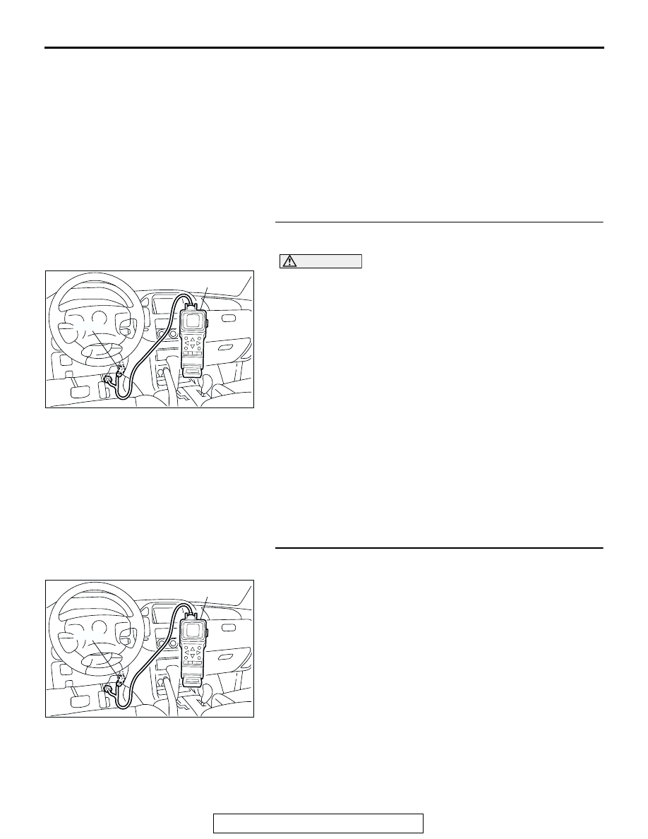
CAUTION
To prevent damage to scan tool MB991502, always turn the
ignition switch to the "LOCK" (OFF) position before con-
necting or disconnecting scan tool MB991502.
(1) Connect scan tool MB991502 to the data link connector.
(2) Start the engine and run at idle.
(3) Set scan tool MB991502 to the data reading mode for item
12, Volume Airflow Sensor.
(4) Warm up the engine to normal operating temperature: 80
°C
to 95
°C (176°F to 203°F).
• When idling, between 17 and 43 Hz (between 3.5 and
7.5 gm/s).
• When 2,500 r/min, between 64 and 104 Hz (between
13.6 and 19.6 gm/s).
(5) Turn the ignition switch to the "LOCK" (OFF) position.
Q: Is the sensor operating properly?
YES : YES: Go to Step 2.
NO : Refer to , DTC P0101
− Volume Airflow Circuit Range/
Performance Problem
, DTC P0102
−
Volume Airflow Circuit Low Input
STEP 2. Using scan tool MB991502, check data list item 13:
Intake Air Temperature Sensor.
(1) Turn the ignition switch to the "ON" position.
(2) Set scan tool MB991502 to the data reading mode for item
13, Intake Air Temperature Sensor.
• The intake air temperature and temperature shown with
the scan tool should approximately match.
(3) Turn the ignition switch to the "LOCK" (OFF) position.
Q: Is the sensor operating properly?
YES : Go to Step 3.
NO : Refer to , DTC P0111
− Intake Air Temperature Circuit
Range/Performance Problem
, DTC P0112
− Intake Air Temperature Circuit Low Input
,
DTC P0113
− Intake Air Temperature Circuit High
Input
ACX01539
16-PIN
MB991502
AC
ACX01539
16-PIN
MB991502
AC