Mitsubishi Montero (2002-2004). Manual - part 621


  Index      Mitsubishi     Mitsubishi Montero - service repair manual 2002-2004 year


Search            


Content   ..  619  620  621  622   ..


Mitsubishi Montero (2002-2004). Manual - part 621


TSB Revision

DIAGNOSTIC TROUBLE CODE PROCEDURES

13Ac-181

DIAGNOSIS

Required Special Tool:

• MB991316: Test Harness

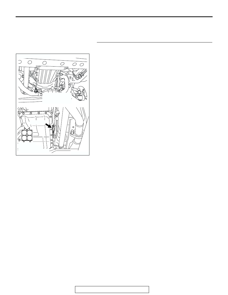
STEP 1. Check harness connector C-14 at the right bank 
heated oxygen sensor (rear) for damage.
Q: Is the harness connector in good condition?

YES : Go to Step 2.
NO :  Repair or replace it. Refer to GROUP 00E, Harness 

Connector Inspection 

P.00E-2

. Then go to Step 12. 

AK201276

1

2

3

4

CONNECTOR: C-14

C-14(GR)

AB

HARNESS 
CONNECTOR: 
COMPONENT SIDE

RIGHT BANK
HEATED OXYGEN
SENSOR (REAR)

TSB Revision

DIAGNOSTIC TROUBLE CODE PROCEDURES

13Ac-182

STEP 2. Check the right bank heated oxygen sensor (rear).

(1) Disconnect right bank heated oxygen sensor (rear) 

connector C-14 and connect test harness special tool, 
MB991316, to the connector on the right bank heated 
oxygen (rear) sensor side.

(2) Measure the resistance between heated oxygen sensor 

connector terminal No. 1 (red clip) and terminal No. 3 (blue 
clip).

Standard value: 11 

 18 ohms [at 20°C (68°F)]

Q: Is the measured resistance between 11 and 18 ohms [at 

20

°C (68°F)]?

YES : Go to Step 3.
NO :  Replace the right bank heated oxygen sensor (rear). 

Then go to Step 12.

AK201276

1

2

3

4

CONNECTOR: C-14

C-14(GR)

AB

HARNESS 
CONNECTOR: 
COMPONENT SIDE

RIGHT BANK
HEATED OXYGEN
SENSOR (REAR)

AKX01624 AB

MB991316

HEATED
OXYGEN
SENSOR
EQUIPMENT
SIDE
CONNECTOR

BLUE

RED

TSB Revision

DIAGNOSTIC TROUBLE CODE PROCEDURES

13Ac-183

STEP 3. Measure the power supply voltage at right bank 
heated oxygen sensor (rear) harness side connector C-14.
(1) Disconnect the connector C-14 and measure at the harness 

side.

(2) Turn the ignition switch to the "ON" position.

(3) Measure the voltage between terminal No. 1 and ground.

• Voltage should be battery positive voltage.

(4) Turn the ignition switch to the "LOCK" (OFF) position.
Q: Is battery positive voltage (approximately 12 volts) 

present?
YES : 
Go to Step 5.
NO :  Go to Step 4.

STEP 4. Check harness connector B-22X at the MFI relay 
for damage.
Q: Is the harness connector in good condition?

YES : Check harness connectors E-114 and D-116 at 

intermediate connector for damage, and repair or 
replace as required. Refer to GROUP 00E, Harness 
Connector Inspection 

P.00E-2

. If intermediate 

connectors E-114 and D-116 are in good condition, 
repair harness wire between MFI relay connector B-
22X (terminal No. 1) and right bank heated oxygen 
sensor (rear) connector C-14 (terminal No. 1) 
because of open circuit or short circuit to ground. 
Then go to Step 12.

NO :  Repair or replace it. Refer to GROUP 00E, Harness 

Connector Inspection 

P.00E-2

. Then go to Step 12. 

AK201276

1

2

3

4

CONNECTOR: C-14

C-14(GR)

AB

HARNESS 
CONNECTOR: 
COMPONENT SIDE

RIGHT BANK
HEATED OXYGEN
SENSOR (REAR)

AKX01496

C-14 HARNESS 
CONNECTOR: 
COMPONENT SIDE

1

2

3

4

AQ

AK200951

2 1

3

4

B-22X

AB

CONNECTOR: B-22X

HARNESS 
CONNECTOR: 
COMPONENT SIDE

TSB Revision

DIAGNOSTIC TROUBLE CODE PROCEDURES

13Ac-184

STEP 5. Measure the power supply voltage at PCM 
connector D-132 by backprobing.
(1) Do not disconnect the connector D-132.
(2) Turn the ignition switch to the "ON" position.

(3) Measure the voltage between terminal No. 24 and ground 

by backprobing.

• Voltage should be battery positive voltage.

(4) Turn the ignition switch to the "LOCK" (OFF) position.
Q: Is battery positive voltage (approximately 12 volts) 

present?
YES : 
Go to Step 8.
NO :  Go to Step 6.

STEP 6. Check harness connector D-132 at PCM for 
damage.
Q: Is the harness connector in good condition?

YES : Go to Step 7.
NO :  Repair or replace it. Refer to GROUP 00E, Harness 

Connector Inspection 

P.00E-2

. Then go to Step 12. 

AK200938

2

3

4

5

6

7

8

9

1

10

14

15

16

17

18

19

20

21

22

23

24

25

26

27

11

12

13

AB

CONNECTOR: D-132

HARNESS CONNECTOR: 
COMPONENT SIDE

PCM

D-132(GR)

AK201409

1

2

3

5

6 7 8 9

4

20

21 22

232425

2627

10111213

14 15

16 1718

19

D-132 HARNESS 
CONNECTOR: 
HARNESS SIDE

AB

AK200938

2

3

4

5

6

7

8

9

1

10

14

15

16

17

18

19

20

21

22

23

24

25

26

27

11

12

13

AB

CONNECTOR: D-132

HARNESS CONNECTOR: 
COMPONENT SIDE

PCM

D-132(GR)


Content   ..  619  620  621  622   ..