Mitsubishi Montero (2002-2004). Manual - part 504


  Index      Mitsubishi     Mitsubishi Montero - service repair manual 2002-2004 year


Search            


Content   ..  502  503  504  505   ..


Mitsubishi Montero (2002-2004). Manual - part 504


REAR WINDOW DEFOGGER

TSB Revision

CHASSIS ELECTRICAL

54A-187

5. Turn the teeth side of the rack cable toward the front of the 

vehicle (90 degree angle to the right), and engage the rack 
cable with the motor gears.

6. Pull lightly on the rack cable. If there is no resistance and it 

comes out, it is not engaged with the motor gears. Check 
that the end of the rack gear is not bent again, and then 
repeat steps (3) and (4) above again.

7. Set up the antenna pole vertically, and turn the radio off to 

wind in the rack cable. The antenna pole will e pulled into 
the motor antenna as the rack cable is wound in.

8. After tightening the ring nut, turn the radio on and off and 

heck the operation of the antenna pole.

REAR WINDOW DEFOGGER

ON-VEHICLE SERVICE

PRINTED-HEATER LINES CHECK

M1543001800139

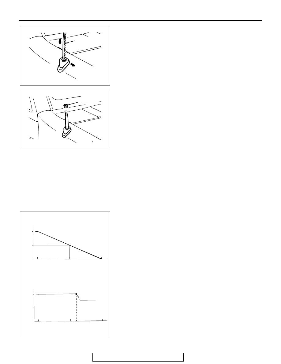
1. Run engine at 2,000 r/min. Check heater element with 

battery at full.

2. Turn "ON "rear window defogger switch. Measure heater 

element voltage with circuit tester at rear window glass 
centre A. Condition is good if it indicates about 6 V.

3. If 12 V is indicated at A, there is a break in the negative 

terminals from A. Move test bar slowly to negative terminal 
to detect where voltage changes suddenly (0V).

4. If 0 V is indicated at A, there is a break in the positive 

terminals from A. Defect where the voltage changes 
suddenly (12 volts, battery positive voltage) in the same 
method described above.

ACX01952 AC

RACK CABLE

VEHICLE FRONT 
DIRECTION

ACX01951AB

RING NUT

ACX00813

NORMAL CHARACTERSTIC CURVE

ABNORMAL CHARACTERSTIC CURVE

VOLTAGE

A (CENTER POINT)

APPROXIMATELY
                         6 V

NEGATIVE
TERMINAL

PRINTED 
HEATER
LINE

POSITIVE
TERMINAL

NEGATIVE
TERMINAL

PRINTED 
HEATER
LINE

POSITIVE
TERMINAL

OPENCIRCUIT 
POINT

VOLTAGE

AC

REAR WINDOW DEFOGGER

TSB Revision

CHASSIS ELECTRICAL

54A-188

REAR WINDOW DEFOGGER SWITCH

 REMOVAL AND INSTALLATION

M1543006200217

<Vehicles with manual A/C>

Refer to GROUP 55A, Heater Control Assembly and 
Blower Switch Assembly 

P.55A-126

.

<Vehicles with auto A/C>

Refer to GROUP 55B, A/C Control Panel, A/C Con-
trol Unit 

P.55B-136

.

INSPECTION

M1543019501835

REAR WINDOW DEFOGGER SWITCH CHECK

REAR WINOW DEFOGGER RELAY CONTINUITY 
CHECK

SWITCH POSITION

TESTER 
CONNECTION

SPECIFIED 
CONDITION

OFF

11 

− 12

Open circuit

ON

11 

− 12

Less than 2 ohms

1

2

3

4

5

6

7

8

9

10 11 12

ACX02300

AC

HEATER CONTROL ASSEMBLY 
CONNECTORT

BATTERY 
VOLTAGE

TESTER 
CONNECTION 

SPECIFIED 
CONDITION

Not applied

− 5

Open circuit

• Connect terminal 1 to 

the positive battery 
terminal

• Connect terminal 3 to 

the negative battery 
terminal

− 5

Less than 2 ohms

ACX01474

1

2

3

4
5

1

2

3

5

ACX01962

DEFOGGER
RELAY

AB

RV METER

TSB Revision

CHASSIS ELECTRICAL

54A-189

RV METER

RV METER DIAGNOSIS

INTRODUCTION TO RV METER

M1543009901003

The RV meter has the following function for the fail-
ure diagnosis service, and is used for the system 
check of units such as the main body and the sensor. 
By virtue of this service function, the cause of failure 
can be conjectured. 

FAILURE DIAGNOSIS SERVICE 
FUNCTION

The RV meter is equipped with the following func-
tions for the failure diagnosis service. 

.

Start service function
1. Press the "ADJ" switch with the ignition switch at "LOCK" 

(OFF) position, and while keeping on pressing, turn the 
ignition switch to the "ACC" or "ON." position. When the ADJ 
switch is pressed continuously for more than five seconds, 
the service function is activated at the same time with the 
reception signal (pip sound) and the first menu screen of the 
service mode is displayed.

2. When respective function switches are pressed on this 

screen, the screen is switched as follows.

• When the function switch 1 [AUTO] is pressed, the screen 

is switched to the automatic check mode.

• When the function switch 2 [DIAG] is pressed, the screen is 

switched to the diagnosis mode.

• When the function switch 3 [HISTORY] is pressed, the 

screen is switched to the history mode.

• When the "ADJ" switch [NEXT] is pressed, the screen is 

switched to the service mode second menu screen.

• When the "DISP" switch [NEXT] is pressed, the service 

mode is terminated.

3. When the function switch 1 is pressed on this screen, the 

screen is switched as follows.

• When the function switch 1 [MONITOR] is pressed, the 

screen is switched to the monitor check mode.

• When the "ADJ" switch [BACK] is pressed, the screen is 

switched to the service mode first menu screen.

• When the "DISP" switch [END] is pressed, the service 

mode is terminated.

.

FUNCTION

CONTENTS

Service 
function

Automatic check mode

Performs communication check and connection check in 
succession.

Diagnosis mode

Performs version check of each unit, vehicle signal check 
and communication and connection check

History mode

Displays the number of errors as the result of 
communication and connection checks 

Monitor check 
mode

Display check mode

Checks whether the screen display function.

Geomagnetic sensor 
check mode

Checks whether the geomagnetism sensor are working 
normally.

Service mode

ACX01984

AUTO

DIAG.

HISTORY

NEXT

END

AE

SERVICE MODE FIRST MENU SCREEN

Service mode

ACX01985

MONITOR

BACK

END

AB

SERVICE MODE SECOND MENU SCREEN

RV METER

TSB Revision

CHASSIS ELECTRICAL

54A-190

Automatic check mode
1. Press the "ADJ" switch with the ignition switch at "LOCK" 

(OFF) position, and while keeping on pressing, turn the 
ignition switch to the "ACC" or "ON." position. When the" 
ADJ" switch is pressed continuously for more than five 
seconds, the service function is activated at the same time 
with the reception signal (pip sound) and the first menu 
screen of the service mode is displayed.

2. Press the function switch 1 [AUTO] on the service mode first 

menu screen. The screen is switched to the automatic check 
mode. Follow the on-screen instructions to turn the ignition 
switch to "ON." position. 

3. Press the ignition switch is turned "ON." The communication 

and connection checks are performed. The checks will be 
finished with 10 seconds.

4. After the communication check and connection check are 

completed, the check results are displayed. Air-conditioner 
input (Auto, manual or less are displayed.) Fuel gauge input 
(OK, full or disconnected are displayed.)
NOTE: 

.

Auto: Automatic A/C
Manual or less: No-automatic A/C circuit or automatic A/C 

circuit open

OK: Some fuel in tank.
Full or Disconnected: Full tank of fuel or fuel level circuit 

open.

5. Press the function switch 1 [NEXT]. The unit status is 

displayed.
NOTE: 

.

Monitor: RV meter
A/C: Automatic A/C

DISPLAY EXAMPLE

CONTENTS OR CONDITION

OK

System check OK

NG

Some kind of error exists, further 
diagnosis required

E1

Communication error

E2

Open circuit or disconnected

Service mode

ACX01984

AUTO

DIAG.

HISTORY

NEXT

END

AE

SERVICE MODE FIRST MENU SCREEN

Checking the system connection.

ACX01986

Please Wait!

AB

Connection status

A/C : Manual or less
Fuel : Full or Disconnected

ACX01987

NEXT

AB

Unit status

Monitor
A/C

: NG
: E2

ACX01988

NEXT

AB


Content   ..  502  503  504  505   ..