Mitsubishi Montero (2002-2004). Manual - part 498


  Index      Mitsubishi     Mitsubishi Montero - service repair manual 2002-2004 year


Search            


Content   ..  496  497  498  499   ..


Mitsubishi Montero (2002-2004). Manual - part 498


RADIO WITH TAPE PLAYER AND CD PLAYER

TSB Revision

CHASSIS ELECTRICAL

54A-163

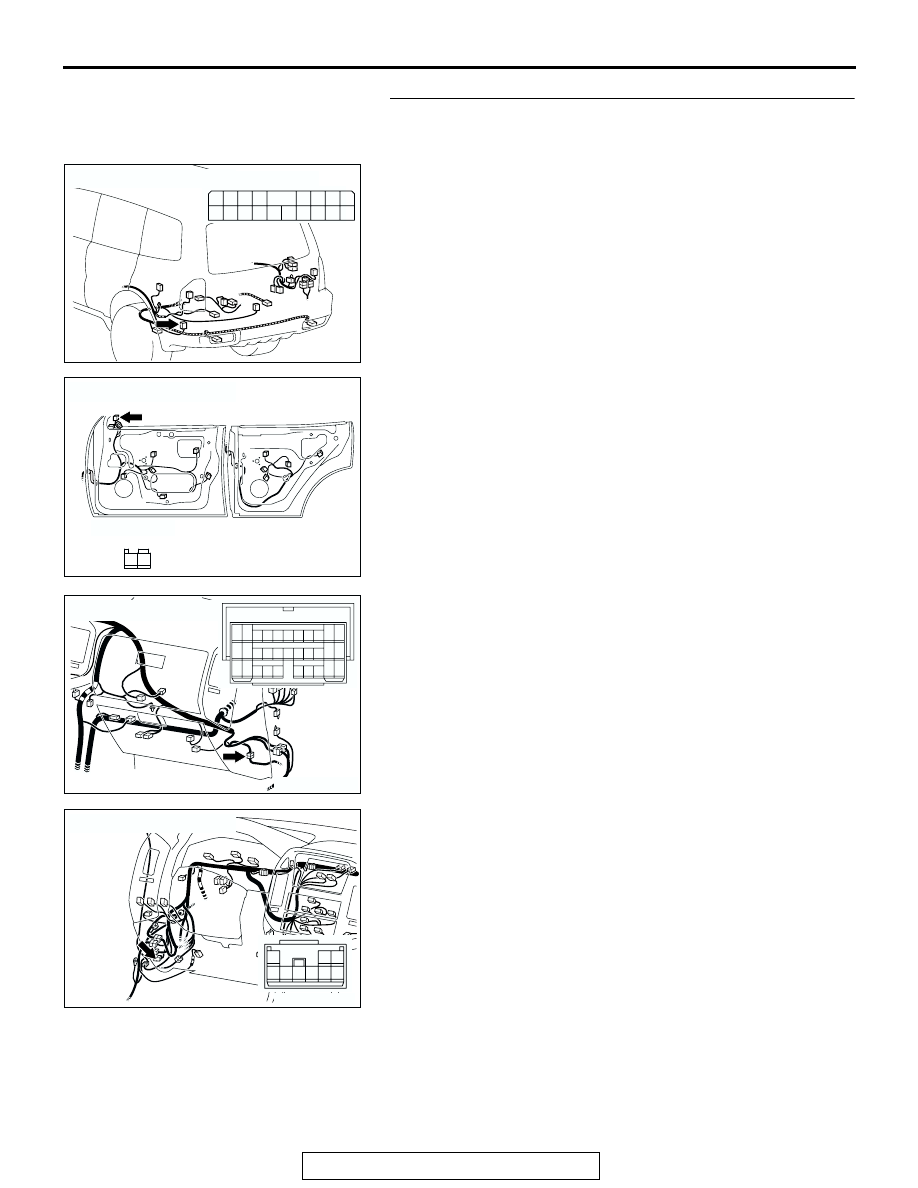
STEP 24. Check the wiring harness between tweeter (RH) 
connector H-15 (terminals 1 and 2) and amplifier connector 
G-19 (terminals 12 and 4).

NOTE: Also check intermediate connectors D-15 and D-124. If 
intermediate connector D-15 or D-124 are damaged, repair or 
replace the connector as described in GROUP 00E, Harness 
Connector Inspection 

P.00E-2

.

Q: Is the wiring harness between tweeter (RH) connector 

H-15 (terminals 1 and 2) and amplifier connector G-19 
(terminals 12 and 4) in good condition?
YES : 
Go to Step 25.
NO :  Repair the wiring harness. The tweeter (RH) should 

sound.

AC204179

CONNECTOR : G-19

AV

HARNESS SIDE

3 2

1110

4

1312

1
9

5

6

1615

7

8

1817

14

AC204181

CONNECTOR :  H-15

AI

HARNESS SIDE

1

2

AC204171

CONNECTOR : D-15

AB

10

9

31

30

20 21

7

6

28

17 18

8

19

29

4

3

25 26

14 15

1

23

12

2

13

24

5

16

27

11

22

32

AC204170

CONNECTOR : D-124

CW

3

9

2

8

6

5

7

4

1

RADIO WITH TAPE PLAYER AND CD PLAYER

TSB Revision

CHASSIS ELECTRICAL

54A-164

STEP 25. Replace the radio and CD player.
Q:  Do the speakers sound?

YES : There is no action to be taken.
NO :  Repair or replace the amplifier. The tweeter (RH) 

should sound.

STEP 26. Check the woofer.
(1) Remove the woofer. Refer to 

P.54A-183

.

(2) Check that the woofer generates noise when a five-volt 

voltage is applied on the woofer terminal.

Q: Is the woofer generating noise?

YES : Go to Step 27.
NO :  Replace the woofer. The woofer should sound.

STEP 27. Check woofer connector G-01 and amplifier 
connector G-19 for loose, corroded or damaged terminals, 
or terminals pushed back in the connector.
Q:  Are woofer connector G-01 and amplifier connector G-

19 in good condition?
YES : 
Go to Step 28.
NO :  Repair or replace the damaged component(s). Refer 

to GROUP 00E, Harness Connector Inspection 

P.00E-2

The woofer should sound.

ACX01868AB

5V

AC204197

CONNECTORS : G-01, G-19

AE

G-19

HARNESS SIDE

G-19

HARNESS SIDE

G-01(B)

2

1

G-01(B)

3 2

1110

4

1312

1
9

5

6

1615

7

8

1817

14

RADIO WITH TAPE PLAYER AND CD PLAYER

TSB Revision

CHASSIS ELECTRICAL

54A-165

STEP 28. Check the wiring harness between woofer 
connector G-01 (terminals 1 and 2) and amplifier connector 
G-19 (terminals 8 and 18).
Q: Is the wiring harness between woofer connector G-01 

(terminal 1 and 2) and amplifier connector G-19 
(terminal 4 and 13) in good condition?
YES : 
Go to Step 29.
NO :  Repair the wiring harness. The woofer should sound.

STEP 29. Replace the radio and CD player.
Q:  Do the speakers sound?

YES : There is no action to be taken.
NO :  Repair or replace the amplifier. The woofer should 

sound.

INSPECTION PROCEDURE 5: Noise is Present while Moving (AM).

STEP 1. Ask the driver about the noise.
(1) Find out the following information from the owner.
(2) Place where the noise occurs.
(3) Locality conditions (valley, mountain, etc.)
(4) Name and frequency of stations affected by noise

Q: What type of noise is detected, vehicle noise or 

external noise?
Vehicle noise : 

It may not be possible to prevent 

noise if the signal is weak. Go to step 2.

External noise : 

In almost all cases, prevention on 

the receiver side is next to impossible when 
the signal is weak. Go to Step 4.

STEP 2. Ask the driver about the location where 
the noise occurs

Q: Does the noise occur when entering or near a 

particular structure (building, tunnel, mountain, 
etc.)?
YES : 

Go to Step 3.

NO : 

Go to Step 4.

AC204197

CONNECTORS : G-01, G-19

AE

G-19

HARNESS SIDE

G-19

HARNESS SIDE

G-01(B)

2

1

G-01(B)

3 2

1110

4

1312

1
9

5

6

1615

7

8

1817

14

RADIO WITH TAPE PLAYER AND CD PLAYER

TSB Revision

CHASSIS ELECTRICAL

54A-166

STEP 3. Check if the noise can be eliminated by 
adjusting the radio.
(1) Adjust the radio as follows.
(2) Change to a different station with a stronger 

signal. This will boost the systems resistance to 
outside interference.

(3) Suppress high tones to reduce noise.

Q: Has the noise been eliminated?

YES : 

The noise has now been eliminated. Inform 

the customer that it is normal to hear noise 
while receiving a weak station.

NO : 

Go to Step 4.

STEP 4. Check for the noise.

Q: Does noise still exist? 

YES : 

If there is still more noise than on other 

similar radio’s find out the type of noise. Ask 
the owner for the name and frequency of the 
affected stations, and consult with the radio 
manufacturer service center.

NO : 

System is operating normally.

INSPECTION PROCEDURE 6: Noise is Present while Moving (FM).

.

DIAGNOSIS
NOTE: FM waves have the same properties as light, 
and can be deflected and blocked. FM signal recep-
tion is severely degraded in the shadow of obstruc-
tions such as buildings or mountains. An FM receiver 
will then only receive a reflected signal.
1. The signal becomes weak as the distance from 

the station's transmission antenna increases. The 
signal strength received depends on the signal 
strength of the transmitting station and intervening 
obstructions such as buildings and hills. Generally 
speaking, the area of good reception is 
approximately 20 

− 25 km (12 − 16 miles) for 

stereo reception, and 30 

− 40 km (19 − 25 miles) 

for monaural reception.

2. The signal will becomes weak when an area of 

shadow from the transmitting antenna (places 
where there are obstructions such as mountains 
or buildings between the station transmitter and 
the vehicle), and noise will appear. <This is called 
first fading, and gives a steady buzzing noise.>

3. If a direct signal hits the antenna at the same time 

as a signal reflected by obstructions such as 
mountains or buildings, interference of the two 
signals will generate noise. When moving, noise 
will appear each time the vehicle's antenna 
passes through this kind of obstructed area. The 
strength and interval of the noise varies according 
to the signal strength and the conditions of 
deflection. <This is called multipath noise, and is a 
repetitive buzzing.>

4. Since FM stereo transmission and reception has a 

weaker field than monaural, it is often 
accompanied by a hissing noise.

After taking measures to prevent the noise, check 
that no noise occurs.
5. Change to a different station with a stronger wave 

to boost resistance to interference.

6. Suppress high tones to reduce noise.
7. Extend antenna completely.
If there is noise, the following causes can be consid-
ered.
8. If due to vehicle noise: It may not be possible to 

prevent noise if the signal is weak.

ACX01869

10kW
OUTPUT FM
BROAD CAST

FOR STEREO:
20 - 25 km
(12 - 16 miles)

FOR  MONAURAL:
30 - 40 km (19 - 25 miles)

FOR  HOME STEREO:
80 - 90 km (50 - 56 miles)

MALTIPATH INTERFERENCE

FIRST FADING
INTERFERENCE

AC


Content   ..  496  497  498  499   ..