Mitsubishi Montero (2002-2004). Manual - part 484


  Index      Mitsubishi     Mitsubishi Montero - service repair manual 2002-2004 year


Search            


Content   ..  482  483  484  485   ..


Mitsubishi Montero (2002-2004). Manual - part 484


SIDE STEP LIGHT

TSB Revision

CHASSIS ELECTRICAL

54A-107

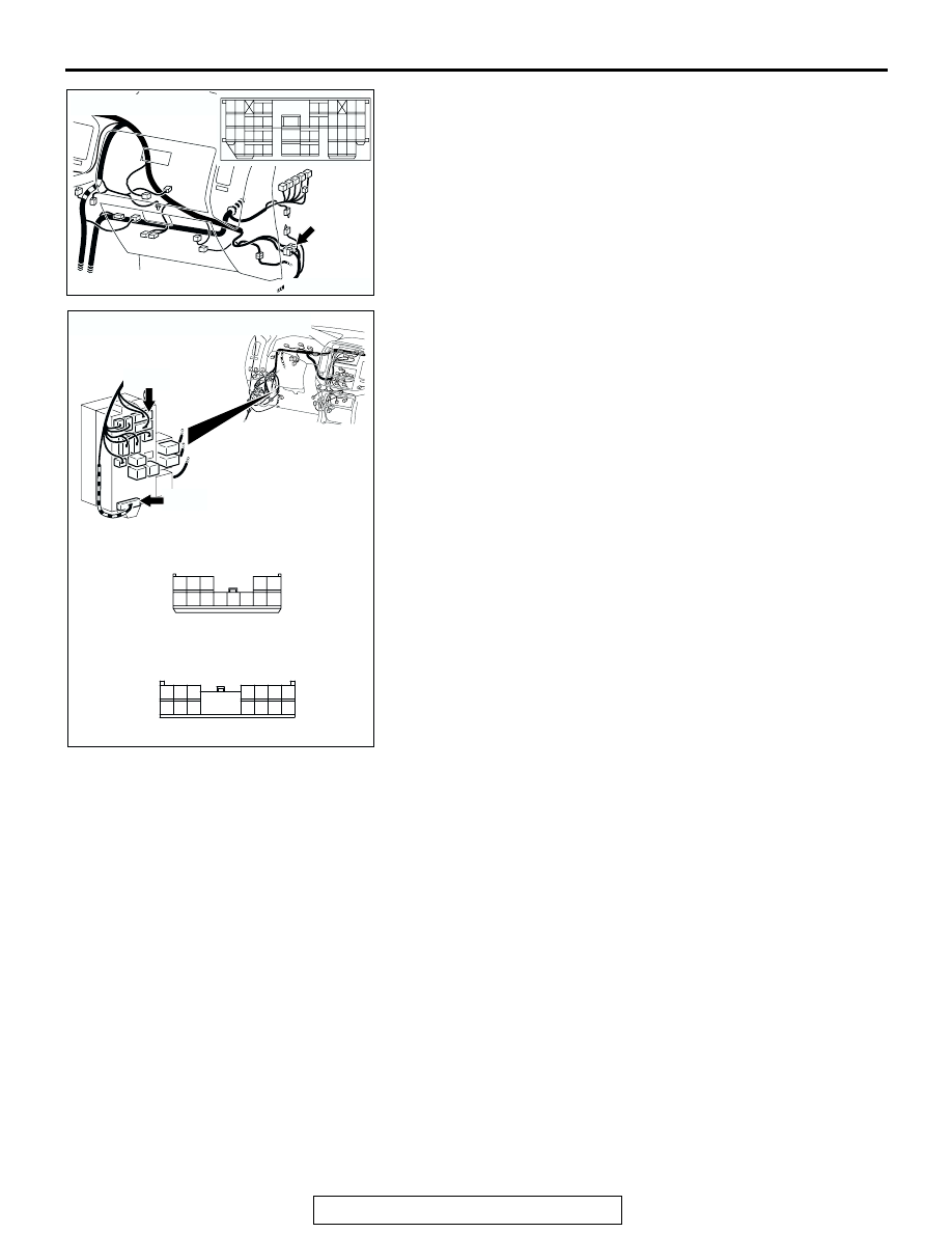
NOTE: Also check intermediate connector D-111, junction 
block connectors D-209 and D-217 for loose, corroded, or dam-
aged terminals, or terminals pushed back in the connector. If 
intermediate connector D-111, junction block connector D-209 
or D-217 is damaged, repair or replace the connector as 
described in GROUP 00E, Harness Connector Inspection 

P.00E-2

.

Q:  Is the wiring harness between side step light-ECU 

connector D-137 (terminal 9) and rear door switch (RH) 
connector F-05 (terminal 2) in good condition?
YES : 
Replace the side step light-ECU. Verify that the side 

step light illuminate normally.

NO :  The wiring harness may be damaged or the 

connector(s) may have loose, corroded or damaged 
terminals, or terminals pushed back in the connector. 
Repair the wiring harness as necessary. Verify that 
the side step light illuminate normally.

AC204171

CONNECTOR : D-111

AC

9

8

6 7

5

3 4

20

32

21

33

43

17 18

30

41

16

29

28

39 40

13

25

12

24

35 36

14

26

37

15

27

38

19

31

42

1

10

22

2

11

23

34

AC204191

CONNECTORS : D-209, D-221

D-209

AH

HARNESS SIDE

HARNESS SIDE

D-217

D-209

D-217

1

2

6

7

9

3

4

11

12

10

5

13

8

8

1

11 10

3

4

12

9

2

13

14

6 5

15

7

SIDE STEP LIGHT

TSB Revision

CHASSIS ELECTRICAL

54A-108

SPECIAL TOOL

M1544000600287

SIDE STEP LIGHT-ECU INSPECTION

M1542012400013

TOOL

TOOL NUMBER 
AND NAME

REPLACED BY MILLER 
TOOL NUMBER 

APPLICATION

MB991223
A: MB991219
B: MB991220 
C: MB991221
D: MB991222
Harness set
A: Test harness
B: LED harness
C: LED harness 

adapter

D: Probe

General service tool 
(jumper)

Making voltage and 
resistance measurements 
during troubleshooting

A: Connect pin contact 

pressure inspection

B: Power circuit 

inspection

C: Power circuit 

inspection

D: Commercial tester 

connection

MB991223

A

B

C

D

AC

AC203981

4

10

1

7 8 9

2 3

12

11

5 6

TERMINAL NO.

SIGNAL

CHECKING REQUIREMENT TERMINAL VOLTAGE

1

Battery power supply

Always

Battery positive voltage

2

Power supply to ignition 
switch (IG1)

Ignition switch "LOCK" (OFF) 
position

0 V

Ignition switch "ON" position

Battery positive voltage

3

Input of lock relay signal 
from ETACS-ECU

When door lock actuator is 
operating (doors locked)

0 V

4

Output to side step light 
(LH)

When side step light (LH) is 
on

2 V or less

5

Output to side step light 
(RH)

When side step light (RH) is 
on

2 V or less

8

Input of unlock relay signal 
from ETACS-ECU

When door lock actuator is 
operating (doors unlocked)

Battery positive voltage

9

Output to all door switch

Ignition switch "LOCK"

0 V

12

Side step light-ECU ground Always

0 V

SIDE STEP LIGHT

TSB Revision

CHASSIS ELECTRICAL

54A-109

ON-VEHICLE SERVICE

BULB REPLACEMENT

M1542001300410

<Side Step LIght Bulb>

1. Turn the bulb socket counterclockwise together with the 

bulb, and remove the bulb.

CAUTION

Do not touch the surface of the bulb with hands or dirty 
gloves as the bulb may pop after a short time. If the sur-
face does become dirty, clean it with alcohol or thinner, 
and let it dry thoroughly before installing.
2. Install the bulb to the bulb socket, and turn the bulb socket 

clockwise together with the bulb.

REMOVAL AND INSTALLATION

M1542012300016

AC204016

AB

SIDE STEP LIGHT 
ASSEMBLY
(REAR VIEW)

AC203940AB

2

1

4

3

6

5

7

4.9 ± 0.9 N·m
43 ± 8 in-lb

4.9 ± 0.9 N·m
43 ± 8 in-lb

2

4

3

6

5

7

SIDE STEP LIGHT REMOVAL 
STEPS

1.

SIDE STEP LIGHT HARNESS 
CONNECTION

2.

SIDE STEP LIGHT BRACKET

3.

SIDE STEP LIGHT ASSEMBLY

4.

SIDE STEP LIGHT UNIT

5.

SIDE STEP LIGHT HARNESS 
AND BULB ASSEMBLY

6.

SIDE STEP LIGHT BULB

7.

SIDE STEP LIGHT HARNESS

SIDE STEP LIGHT REMOVAL 
STEPS (Continued)

RHEOSTAT

TSB Revision

CHASSIS ELECTRICAL

54A-110

RHEOSTAT

REMOVAL AND INSTALLATION

M1542006000210

AC203956AB

8

4.9 ± 0.9 N·m
43 ± 8 in-lb

SIDE STEP LIGHT-ECU 
REMOVAL STEPS

LOWER PANEL (REFER TO 
GROUP 52A, INTERIOR 

P.52A-

2

.)

8.

SIDE STEP LIGHT-ECU

AC204146AB

2

1

AC204146

RHEOSTAT REMOVAL STEPS

1. SWITCH PANEL
2. RHEOSTAT 


Content   ..  482  483  484  485   ..