Mitsubishi Montero (2002-2004). Manual - part 472


  Index      Mitsubishi     Mitsubishi Montero - service repair manual 2002-2004 year


Search            


Content   ..  470  471  472  473   ..


Mitsubishi Montero (2002-2004). Manual - part 472


COMBINATION METERS ASSEMBLY AND VEHICLE SPEED SENSOR

TSB Revision

CHASSIS ELECTRICAL

54A-59

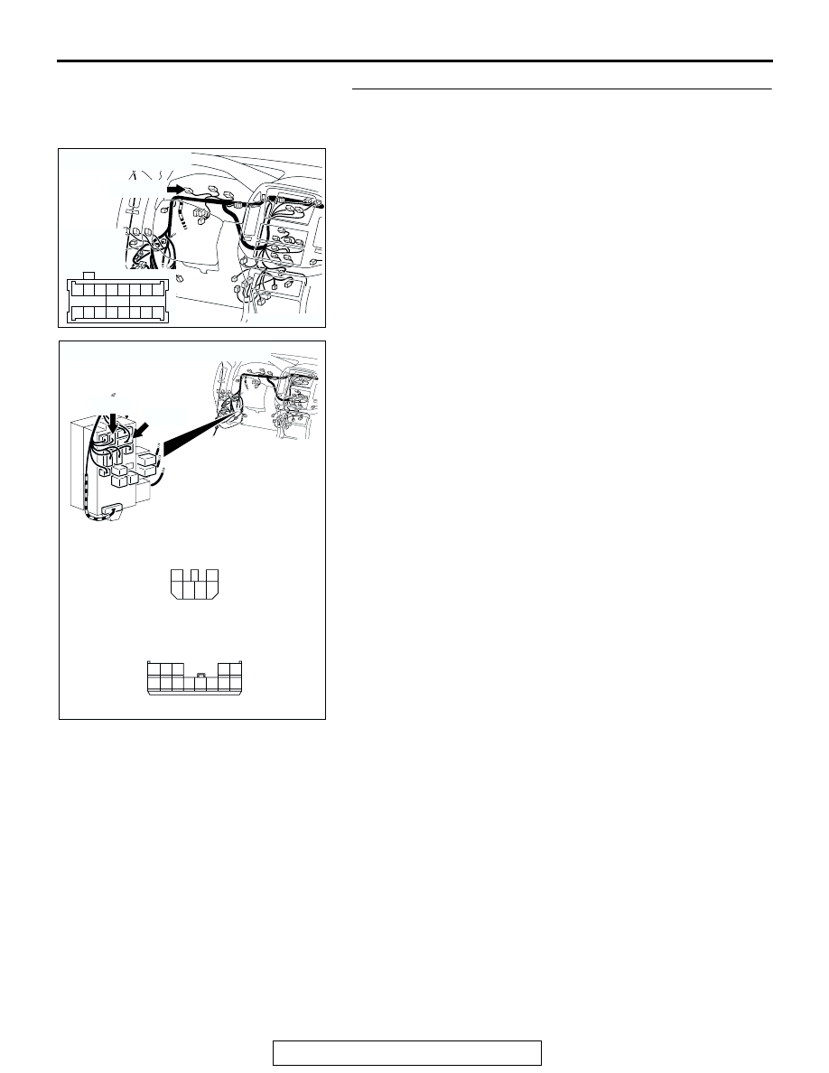
STEP 6. Check the wiring harness between combination 
meter connector D-03 (terminal 62) and ignition switch 
(IG1).

NOTE: Also check junction block connectors D-208 and D-210. 
If junction block connector D-208 or D-210 is damaged, repair 
or replace the connector as described in GROUP 00E, Harness 
Connector Inspection 

P.00E-2

.

Q: Is the wiring harness between combination meter 

connector D-03 (terminal 62) and ignition switch (IG1) in 
good condition?
YES : 
There is no action to be taken.
NO :  Repair the wiring harness. Check to see that all 

meters operate.

AC204170

CONNECTOR : D-03

AC

D-03(GR)

HARNESS 
SIDE

51

52

61 60

53

54

56

57

55

63

66 65 64

59

62

58

67

D-03(GR)

AC204191

CONNECTORS: D-208, D-210

D-208

AC

HARNESS SIDE

HARNESS SIDE

D-210

D-208

D-210

1

2

3

5

6

4

1

2

7 6

3

9

4

11

12

10

13

5

8

COMBINATION METERS ASSEMBLY AND VEHICLE SPEED SENSOR

TSB Revision

CHASSIS ELECTRICAL

54A-60

STEP 7. Measure at combination meter connector D-32 in 
order to check the ground circuit to the combination 
meter. 
(1) Disconnect combination meter connector D-32, and 

measure at the wiring harness side.

(2) Measure the resistance between terminal 25 and ground.

• The resistance should equal 2 ohms or less.

(3) Measure the resistance between terminal 11 and ground.

• The resistance should equal 2 ohms or less.

Q: Is the measured voltage approximately 12 volts (battery 

positive voltage)?
YES : 
Repair the combination meter. Check to see that all 

meters operate.

NO :  Go to Step 8.

STEP 8. Check combination meter connector D-32 for 
loose, corroded or damaged terminals, or terminals 
pushed back in the connector.
Q: Is combination meter connector D-32 in good 

condition?
YES : 
Go to Step 9.
NO :  Repair or replace the damaged component(s). Refer 

to GROUP 00E, Harness Connector Inspection 

P.00E-2

. Check to see that all meters operate.

AC204170

CONNECTOR : D-32

CU

HARNESS SIDE

D-32(GR)

D-32(GR)

3

4

16

17

1

2

14

15

5

7 6

19

13

8

9

21

22

20

18

23

10

11

24

25

12

AC204738 EP

HARNESS SIDE: D-32

3

4

16

17

1

2

14

15

5

7 6

19

13

8

9

21

22

20

18

23

10

11

24

25

12

AC204170

CONNECTOR : D-32

CU

HARNESS SIDE

D-32(GR)

D-32(GR)

3

4

16

17

1

2

14

15

5

7 6

19

13

8

9

21

22

20

18

23

10

11

24

25

12

COMBINATION METERS ASSEMBLY AND VEHICLE SPEED SENSOR

TSB Revision

CHASSIS ELECTRICAL

54A-61

STEP 9. Check the wiring harness between combination 
meter connector D-32 (terminal 25 and 11) and ground.
Q: Is the wiring harness between combination meter 

connector D-32 (terminal 25 and 11) and ground in good 
condition?
YES : 
There is no action to be taken.
NO :  Repair the wiring harness. Check to see that all 

meters operate.

SPECIAL TOOLS

M1543000600950

ON-VEHICLE SERVICE

SPEEDOMETER CHECK

M1543000900296

Adjust the pressure of tires to the specified level. (Refer to 

GROUP 31, On-vehicle Service 

P.31-7

.)

AC204170

CONNECTOR : D-32

CU

HARNESS SIDE

D-32(GR)

D-32(GR)

3

4

16

17

1

2

14

15

5

7 6

19

13

8

9

21

22

20

18

23

10

11

24

25

12

TOOL

TOOL NUMBER 
AND NAME

REPLACED BY 
MILLER TOOL 
NUMBER

APPLICATION

MB991502 Scan tool 
(MUT-II)

DRB-III (Scan tool)

Reading MFI system 
diagnostic trouble code

MB991223
A: MB991219
B: MB991220 
C: MB991221
D: MB991222
Harness set
A: Test harness
B: LED harness
C: LED harness 

adapter

D: Probe

General service tool 
(jumper)

Making voltage and 
resistance 
measurements during 
troubleshooting

A: Connect pin contact 

pressure inspection

B: Power circuit 

inspection

C: Power circuit 

inspection

D: Commercial tester 

connection

B991502

MB991223

A

B

C

D

AC

COMBINATION METERS ASSEMBLY AND VEHICLE SPEED SENSOR

TSB Revision

CHASSIS ELECTRICAL

54A-62

CAUTION

Place the transfer shift lever to "2H" position. 
1. Set the vehicle onto a speedometer tester and use wheel 

chocks to hold the front wheels.

2. To prevent the sideward shaking of the front wheel, attach 

the puller on the towing hook and the tie down hook at front 
side and connect its both ends to the anchor plate.

3. To prevent the jumping out of the vehicle, attach the chain 

and the wire whose both ends are tightly fixed to the rear 
towing hook.

CAUTION

Do not increase/decrease speed rapidly while testing.
4. Check if the speedometer indicator range is within the 

standard values.

Standard value: <Vehicles for U.S.A.>

Standard value: <Vehicles for Canada.>

5. If not to the standard value, inspect for proper tire size. If not 

correct, replace tires with original size tires and retest. If 
correct, replace the speedometer. If still not to standard 
value, replace vehicle speed sensor.

STANDARD INDICATION 
km/h (mph)

ALLOWANCE RANGE 
km/h (mph)

16 (10)

14 

− 18 (8.5 − 11.5)

40 (25) 

38 

− 42 (23.5 − 26.5)

80 (50)

78 

− 83 (48.5 − 51.5)

120 (75)

118 

− 123 (73.5 − 76.5)

161 (100)

158 

− 165 (98.5 − 102.5)

STANDARD INDICATION 
km/h

ALLOWANCE RANGE
km/h

20

19 

− 24

40

40 

− 44

80

80 

− 85

120

120.5 

− 125.5

160

160.5 

− 165.5

ACX01629AB

ACX00775 AB

FRONT

ANCHOR PLATE

PULLER


Content   ..  470  471  472  473   ..