Mitsubishi Montero (2002-2004). Manual - part 466


  Index      Mitsubishi     Mitsubishi Montero - service repair manual 2002-2004 year


Search            


Content   ..  464  465  466  467   ..


Mitsubishi Montero (2002-2004). Manual - part 466


COMBINATION METERS ASSEMBLY AND VEHICLE SPEED SENSOR

TSB Revision

CHASSIS ELECTRICAL

54A-35

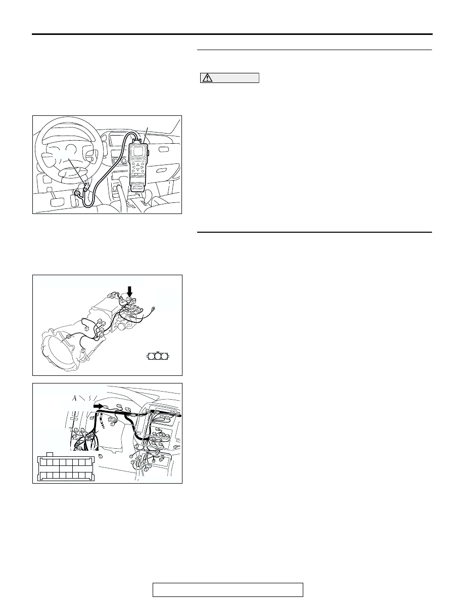
STEP 2. Using scan tool MB991502, check the MFI system 
diagnostic trouble code (DTC).

CAUTION

To prevent damage to the scan tool always turn the igni-
tion switch to "LOCK" (OFF) position before connecting or 
disconnecting the scan tool.

1. Connect scan tool MB991502 to the data link connector. 

2. Turn the ignition switch to the "ON" position.
3. Check the MFI system diagnostic trouble code.

Q: Is DTC P0720 set?

YES : Refer to GROUP 13A 

P.13Ab-2

, Multiport Fuel 

Injection (MFI) Diagnosis.

NO :  Go to Step 3.

STEP 3. Check combination meter connector D-03 and 
vehicle speed sensor connector C-08 for loose, corroded 
or damaged terminals, or terminals pushed back in the 
connector.
Q: Are combination meter connector D-03 and vehicle 

speed sensor connector C-08 in good condition?
YES : 
Go to Step 4.
NO :  Repair or replace the damaged component(s). Refer 

to GROUP 00E, Harness Connector Inspection 

P.00E-2

. The speedometer should work normally.

ACX01539

16-pin

MB991502

AI

AC204395

CONNECTOR : C-08

C-08(B)

C-08(B)

HARNESS SIDE

AI

3 2 1

AC204170

CONNECTOR : D-03

AC

D-03(GR)

HARNESS 
SIDE

51

52

61 60

53

54

56

57

55

63

66 65 64

59

62

58

67

D-03(GR)

COMBINATION METERS ASSEMBLY AND VEHICLE SPEED SENSOR

TSB Revision

CHASSIS ELECTRICAL

54A-36

STEP 4. Check the wiring harness between combination 
meter connector D-03 (terminal 65) and vehicle speed 
sensor connector C-08 (terminal 3).

AC204395

CONNECTOR : C-08

C-08(B)

C-08(B)

HARNESS SIDE

AI

3 2 1

AC204170

CONNECTOR : D-03

AC

D-03(GR)

HARNESS 
SIDE

51

52

61 60

53

54

56

57

55

63

66 65 64

59

62

58

67

D-03(GR)

COMBINATION METERS ASSEMBLY AND VEHICLE SPEED SENSOR

TSB Revision

CHASSIS ELECTRICAL

54A-37

NOTE: Also check intermediate connector E-111, E-114 and 
joint connector (4) D-116. If intermediate connector E-111, E-
114 or joint connector (4) D-116 are damaged, repair or replace 
the connector as described in GROUP 00E, Harness Connec-
tor Inspection 

P.00E-2

.

Q: Is the wiring harness between combination meter 

connector D-03 (terminal 65) and vehicle speed sensor 
connector C-08 (terminal 3) in good condition?
YES : 
Go to Step 5.
NO :  Repair the wiring harness. The speedometer should 

work normally.

STEP 5. Check the speedometer by operating the auto-
cruise control system.
Q:  Does auto-cruise control work normally?

YES : Replace the combination meter. The speedometer 

should work normally.

NO :  Replace the PCM. The speedometer should work 

normally.

AC204171

CONNECTOR : D-116

AD

9 10

8

6 7

31 32

30

29

18 19 20 21

5

4

2

1

3

27

26

24

23

25

12 13 14 15 16 17

28

11
22
33

AC204194

CONNECTORS : E-111, E-114

E-111

AB

E-114

E-111

E-114

10

9

31

30

20 21

7

6

28

17 18

8

19

29

4

3

25 26

14 15

1

23

12

2

13

24

5

16

27

11

22

32

10

9

31

30

20 21

7

6

28

17 18

8

19

29

4

3

25 26

14 15

1

23

12

2

13

24

5

16

27

11

22

32

COMBINATION METERS ASSEMBLY AND VEHICLE SPEED SENSOR

TSB Revision

CHASSIS ELECTRICAL

54A-38

INSPECTION PROCEDURE 2: Tachometer does not Work.

Tachometer Circuit

AC204170

CONNECTORS : D-03, D-29

DE

D-03(GR)

D-29

AC204171

CONNECTOR : D-134

AW

D-134(GR)


Content   ..  464  465  466  467   ..