Mitsubishi Montero (2002-2004). Manual - part 439


  Index      Mitsubishi     Mitsubishi Montero - service repair manual 2002-2004 year


Search            


Content   ..  437  438  439  440   ..


Mitsubishi Montero (2002-2004). Manual - part 439


POWER STEERING GEAR BOX ASSEMBLY

TSB Revision

POWER STEERING

37A-43

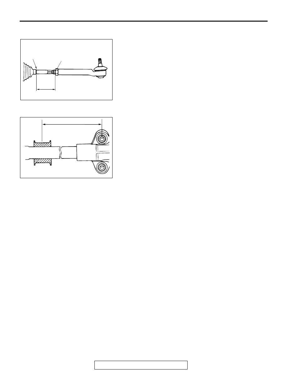
>>N<< TIE ROD END/TIE ROD END JUM NUT 
INSTALLATION
Screw in the tie rod end to achieve the right and left length as 
illustrated. Lock with the lock nut.
NOTE: Tighten the locknut to the specified torque after install-
ing the gear box assembly onto the body and adjusting the toe-
in.

.

>>O<< GEAR MOUNT RUBBER INSTALLATION
Install the gear mount rubber on the race housing so that the 
dimension shown in the illustration can be obtained.

TIE ROD END BALL JOINT DUST COVER 
REPLACEMENT

M1372008200253

If the dust cover is damaged accidentally during service work, 
replace the dust cover as follows:
1. Remove the clip ring and then remove the dust cover.

ACX01140AC

57 mm
(2.2 in)

JUM NUT

BELLOWS
END

ACX01168 AB

390 mm
(15.4 in)

POWER STEERING OIL PUMP ASSEMBLY

TSB Revision

POWER STEERING

37A-44

2. Apply multipurpose grease to the lip and inside of the dust 

cover.

CAUTION

Do not leave grease on the threaded and the knuckle con-
necting portion (tapered portion) of the ball joint. If grease 
is on those portions, wipe it off thoroughly.
3. Apply multipurpose grease on the top of the dust cover and 

the ball joint stud retainer.

4. Wrap the stud screw portion of the tie rod end ball joint with 

vinyl tape to install the dust cover on the tie rod end ball 
joint.

5. Secure the dust cover with the clip ring.

CAUTION

To prevent grease from contacting the knuckle connection 
portion (tapered portion) of the ball joint, do not compress 
the dust cover before installing on the vehicle.
6. Check the dust cover for cracks or damage by pushing it 

with your finger.

POWER STEERING OIL PUMP ASSEMBLY

REMOVAL AND INSTALLATION

M1372005200221

ACX01169AB

CLIP RING

DUST COVER

TAPERED
SECTION

26 mm 
(1.0 in) OR 
LONGER

Pre-removal Operation
• Removal of Battery and Battery Tray

• Power Steering Fluid Draining (Refer to 

P.37A-19

.)

Post-installation Operation
• Power Steering Fluid Line Bleeding (Refer to 

P.37A-19

.)

• Installation of Battery and Battery Tray

• Drive Belt Tension Check (Refer to 

P.37A-18

.)

AC000667

3

2

4

1

22 

± 

4 N

·

m

16 

± 

3 ft-lb

AB

57 

± 

7 N

·

m

42 

± 

5 ft-lb

22 

± 

4 N

·

m

16 

± 

3 ft-lb

REMOVAL STEPS

1. DRIVE BELT (REFER TO GROUP 

11A, TIMING BELT 

P.11A-33

.)

2. CONNECTION OF SUCTION 

HOSE

3. CONNECTION OF PRESSURE 

TUBE 

4. OIL PUMP ASSEMBLY

REMOVAL STEPS (Continued)

POWER STEERING OIL PUMP ASSEMBLY

TSB Revision

POWER STEERING

37A-45

DISASSEMBLY AND ASSEMBLY

M1372005400236

CAUTION

Never disassemble the terminal assembly. It cannot be reassembled.

ACX01167 AC

OIL PUMP CARTRIDGE KIT

OIL PUMP SEAL KIT

7

6

6

3

5

8

4

9

20

11

22

6

16

14

18

12

2

10

7

18

12

17

11

16

15

14

10

2

9

8

13

4

5

3

6

19

1

22

21

20

24 

± 

2 N

·

m

18 

± 

1 ft-lb

9.9 

± 

2.1 N

·

m

88 

± 

18 in-lb

35 

± 

4 N

·

m

26 

± 

3 ft-lb

44 

± 

5 N

·

m

32 

± 

4 ft-lb

37 

± 

2 N

·

m

27 

± 

2 ft-lb

28 

± 

2 N

·

m

20 

± 

2 ft-lb

OIL PUMP PULLEY AND SHAFT KIT

: GENUINE MITSUBISHI POWER STEERING FLUID

DISASSEMBLY STEPS

1. PUMP COVER
2. O-RING
3. ADAPTER RING

>>E<<

4. VANES

>>D<<

5. CAM RING
6. SNAP RING

7. PULLEY AND SHAFT

>>C<<

8. ROTOR
9. SIDE PLATE

>>A<<

10. O-RING 

>>A<<

11. O-RING

>>B<<

12. OIL SEAL

DISASSEMBLY STEPS (Continued)

POWER STEERING OIL PUMP ASSEMBLY

TSB Revision

POWER STEERING

37A-46

Required Special Tools:

• MB990938: Bearing and Oil Seal Installer

• MB991203: Oil Seal and Bearing Installer

ASSEMBLY SERVICE POINTS

.

>>A<< O-RING INSTALLATION

.

13. TERMINAL ASSEMBLY

>>A<<

14. O-RING
15. INNER PLUG A

>>A<<

16. O-RING
17. INNER PLUG B

>>A<<

18. O-RING
19. INNER PLUG C

>>A<<

20. O-RING

DISASSEMBLY STEPS (Continued)

21. SUCTION CONNECTOR

>>A<<

22. O-RING

DISASSEMBLY STEPS (Continued)

NO.

ID 

× WIDTH mm (in)

1

6.8 

× 1.9 (0.27 × 0.07)

2

INNER PLUG A, C 12.4 

× 2.6 (0.49 × 0.10)

INNER PLUG B

14.8 

× 2.4 (0.58 × 0.09)

3

21 

× 1.9 (0.83 × 0.07)

4

14.8 

× 1.9 (0.58 × 0.07)

5

3.8 

× 1.9 (0.15 × 0.07)

6

15.8 

× 2.4 (0.62 × 0.09)

7

9.8 

× 1.9 (0.39 × 0.07)

8

6.8 

× 1.9 (0.27 × 0.07)

AC203965

SIDE PLATE

SUCTION CONNECTOR

PUMP BODY

3

1 (C)

6

5

4

7

8

AB

2 (A,B,C)

TERMINAL 
ASSEMBLY

INNER PLUG
A,B,C


Content   ..  437  438  439  440   ..