Mitsubishi Montero (2002-2004). Manual - part 424


  Index      Mitsubishi     Mitsubishi Montero - service repair manual 2002-2004 year


Search            


Content   ..  422  423  424  425   ..


Mitsubishi Montero (2002-2004). Manual - part 424


REAR SUSPENSION ASSEMBLY

TSB Revision

REAR SUSPENSION

34-9

REMOVAL SERVICE POINTS

.

<<A>> BRAKE CALIPER ASSEMBLY REMOVAL
Secure the removed caliper assembly with a wire, so that it 
does not fall.

.

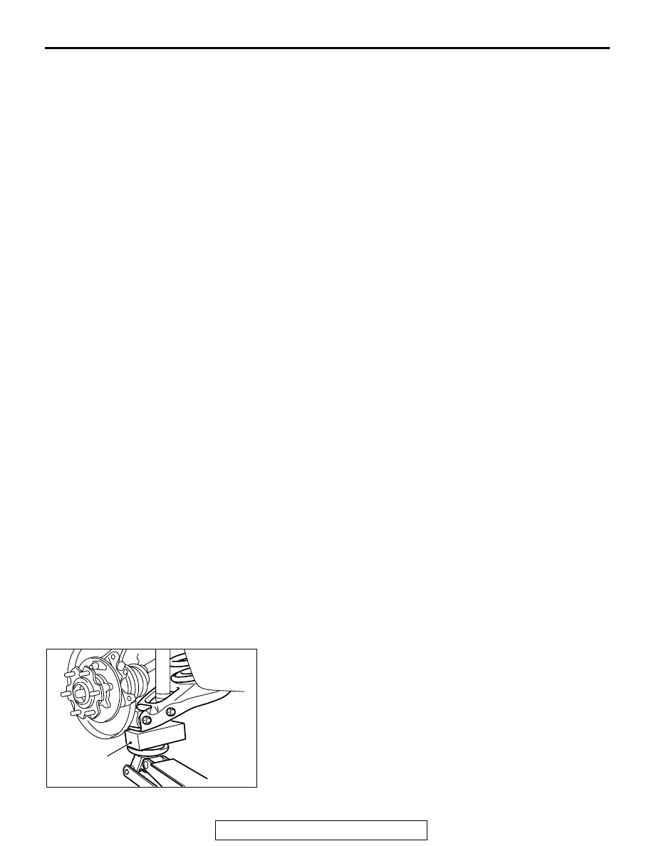
<<B>> LOWER ARM MOUNTING BOLT REMOVAL
1. Place a piece of wood at the lower arm as shown in the 

illustration. Using the floor jack, compress the coil spring to 
remove the lower arm mounting bolt.

2. Lower the floor jack slowly, and then remove the coil spring.

.

8.

ADJUSTER ASSEMBLY (REFER 
TO GROUP 36, PARKING BRAKE 
LINING AND DRU

P.36-7

.)

9.

STRUT (REFER TO GROUP 36, 
PARKING BRAKE LINING AND 
DRUM 

P.36-7

.)

10. SHOE-TO-SHOE SPRING 

(REFER TO GROUP 36, PARKING 
BRAKE LINING AND DRUM 

P.36-

7

.)

11. SHOE HOLD-DOWN CUP (REFER 

TO GROUP 36, PARKING BRAKE 
LINING AND DRU

P.36-7

.)

12. SHOE HOLD-DOWN PIN (REFER 

TO GROUP 36, PARKING BRAKE 
LINING AND DRU

P.36-7

.)

13. SHOE AND LINING ASSEMBLY 

(REFER TO GROUP 36, PARKING 
BRAKE LINING AND DRUM 

P.36-

7

.)

14. PARKING BRAKE CABLE 

CONNECTION

15. SHOCK ABSORBER MOUNTING 

BOLT

<<B>>

>>A<<

16. LOWER ARM MOUNTING BOLT
17. SPRING UPPER PAD

>>A<<

18. COIL SPRING
19. SPRING LOWER PAD

<<C>>

20. BOLT ASSEMBLY (CAMBER 

ADJUSTING BOLT)

21. LOWER ARM ASSEMBLY
22. TRAILING ARM MOUNTING NUT
23. STOPPER

<<D>>

24. CROSSMENBER MOUNTING 

NUT

25. REAR SUSPENSION ASSEMBLY

REMOVAL STEPS (Continued)

AC204512 AB

PIECE OF 
WOOD

REAR SUSPENSION ASSEMBLY

TSB Revision

REAR SUSPENSION

34-10

<<C>> BOLT ASSEMBLY (CAMBER ADJUSTING BOLT) 
REMOVAL
Make the mating marks to the bracket and the camber adjust-
ing bolt, and then remove the camber adjusting bolt.

.

<<D>> CROSSMEMBER MOUNTING NUT REMOVAL
Support the crossmember with a garage jack or transmission 
jack to remove the crossmember mounting nut.

INSTALLATION SERVICE POINT

.

>>A<< COIL SPRING/LOWER ARM MOUNTING BOLT 
INSTALLATION
1. The identification color of the coil spring should be located at 

the lower side.

2. Align the coil spring end with the spring lower pad cavity.
3. Place a piece of wood at the lower arm as shown in the 

illustration. Using the floor jack, compress the coil spring to 
remove the lower arm mounting bolt.

INSPECTION

M1341015500067

Check crossmember for cracks or other damage.

ACX00734AB

LOWER ARM

CAMBER 
ADJUSTMENT 
BOLT

AC102289

AC204512 AB

PIECE OF 
WOOD

UPPER ARM ASSEMBLY

TSB Revision

REAR SUSPENSION

34-11

UPPER ARM ASSEMBLY

 REMOVAL AND INSTALLATION

M1341003600164

Required Special Tool:

• MB991897: Ball Joint Remover

Pre-removal Operations
• Brake Fluid Draining

Post-installation Operations
• Press the dust cover with your finger to check that there 

are no cracks or damage in the dust cover.

• Brake fluid refilling and air bleeding (Refer to GROUP 

35A, On-vehicle Service 

P.35A-122

.)

• Wheel Alignment Check and Adjustment (Refer to 

P.34-

6

.) 

ACX00735

15 

± 

2 N

·

m

11 

± 

2 ft-lb

167 

± 

10 N

·

m

124 

± 

7 ft-lb

104 

± 

14 N

·

m

77 

± 

10 ft-lb

98 

± 

12 N

·

m

72 

± 

9 ft-lb

1

8

2

9

4

10

7

6

3

8

2

5

10

AB

167 

± 

10 N

·

m

124 

± 

7 ft-lb

150 

± 

30 N

·

m

111 

± 

22 ft-lb

REMOVAL STEPS

1. BRAKE PIPE CONNECTION
2. CLIP
3. REAR WHEEL SPEED SENSOR 

AND UPPER ARM ASSEMBLY 
CONNECTION.

4. BUMP STOPPER
5. STABILIZER LINK AND UPPER ARM 

ASSEMBLY CONNECTION.

6. COTTER PIN

<<A>>

7. UPPER ARM BALL JOINT AND 

KNUCKLE CONNECTION

<<B>> >>A<<

8. UPPER ARM ASSEMBLY AND 

REAR FRAME CONNECTION

9. UPPER ARM
10. UPPER ARM BALL JOINT 

REMOVAL STEPS (Continued)

UPPER ARM ASSEMBLY

TSB Revision

REAR SUSPENSION

34-12

REMOVAL SERVICE POINTS

.

<<A>> UPPER ARM BALL JOINT AND KNUCKLE DISCON-
NECTION

CAUTION

• Do not remove the nut from ball joint. Loosen it and use 

special tool MB991897 to avoid possible damage to ball 
joint threads.

• Hang special tool MB991897 with a cord to prevent it 

from falling. 

1. Install special tool MB991897 as shown in the figure.

2. Turn the bolt and knob as necessary to make the jaws of 

special tool MB991897 parallel, tighten the bolt by hand and 
confirm that the jaws are still parallel.
NOTE: When adjusting the jaws in parallel, make sure the 
knob is in the position shown in the figure.

3. Tighten the bolt with a wrench to disconnect the ball joint.

.

<<B>> UPPER ARM ASSEMBLY AND REAR FRAME 
DISCONNECTION
Disconnect the connection of the DOJ assembly and the com-
panion shaft assembly.

AC106820 AB

CORD

BOLT

MB991897

NUT

BALL JOINT

AC106821

KNOB

PARALLEL

BOLT

GOOD

BAD

AB

ACX00736AB

COMPANION
SHAFT 
ASSEMBLY

DOJ ASSEMBLY


Content   ..  422  423  424  425   ..