Mitsubishi Montero (2002-2004). Manual - part 326


  Index      Mitsubishi     Mitsubishi Montero - service repair manual 2002-2004 year


Search            


Content   ..  324  325  326  327   ..


Mitsubishi Montero (2002-2004). Manual - part 326


SYMPTOM PROCEDURES

TSB Revision

SWS SYMPTOM PROCEDURES

54Bb-351

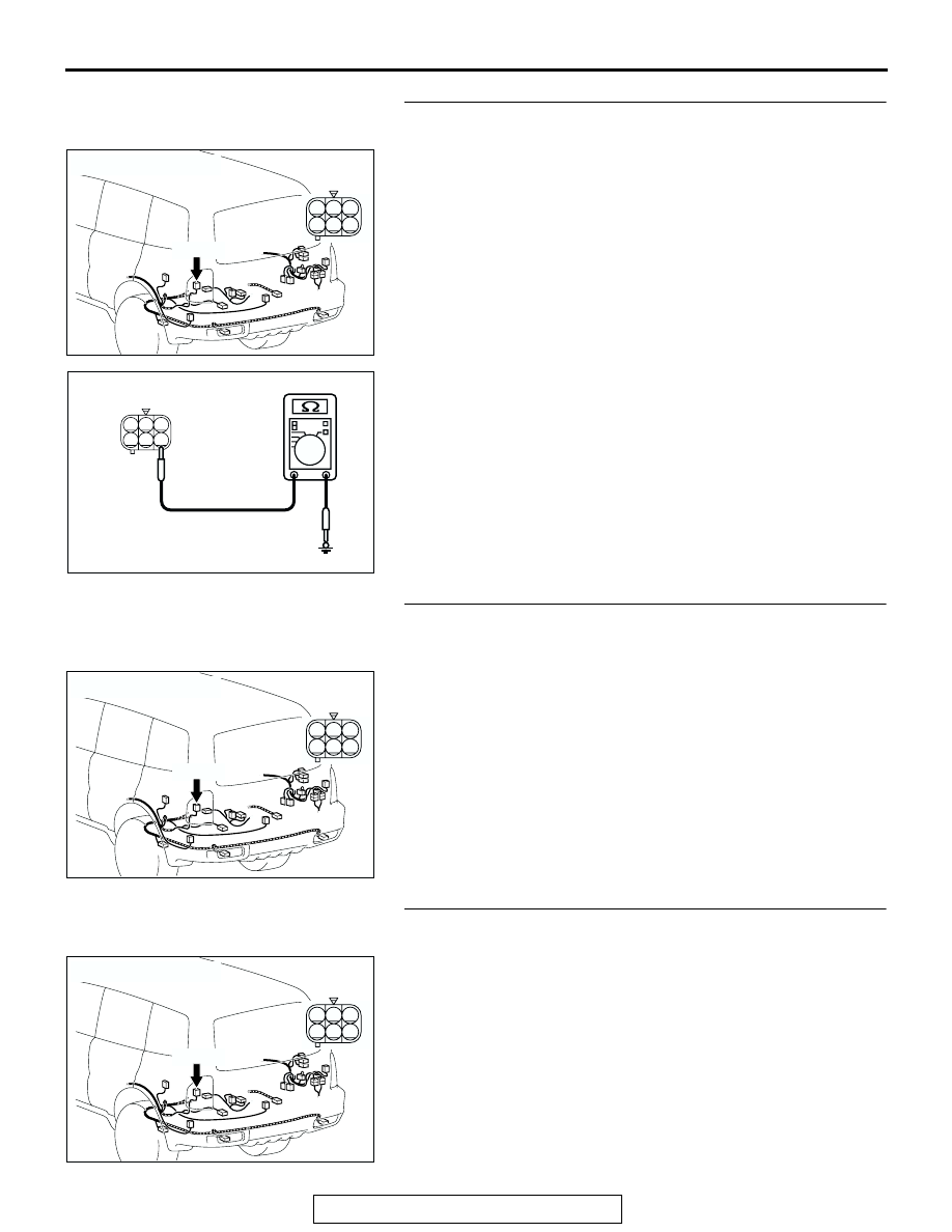
STEP 45. Check the ground circuit to the side marker light 
(LH). Test at side marker light (LH) connector G-02. 
(1) Disconnect side marker light (LH) connector G-02 and 

measure the resistance available at the wiring harness side 
of the connector.

(2) Measure the resistance value between terminal 4 and 

ground.

• The resistance should equal 2 ohms or less.

Q: Is the measured resistance 2 ohms or less?

YES : Go to Step 48.
NO :  Go to Step 46.

STEP 46. Check side marker light (LH) connector G-02 for 
loose, corroded or damaged terminals, or terminals 
pushed back in the connector.
Q: Is side marker light (LH) connector G-02 in good 

condition?
YES : 
Go to Step 47.
NO :  Repair or replace the damaged component(s). Refer 

to GROUP 00E, Harness Connector Inspection 

P.00E-2

. Verify that the side marker lights (LH) 

illuminates normally.

STEP 47. Check the wiring harness between side marker 
light (LH) connector G-02 (terminal 4) and ground.
Q: Is the wiring harness between side marker light (LH) 

connector G-02 (terminal 4) and ground in good 
condition?
YES : 
Replace the side marker light socket. Verify that the 

side marker light (LH) illuminates normally.

NO :  The wiring harness may be damaged or the 

connector(s) may have loose, corroded or damaged 
terminals, or terminals pushed back in the connector. 
Repair the wiring harness as necessary. Verify that 
the side marker light (LH) illuminates normally.

AC204179

CONNECTOR : G-02

AB

HARNESS SIDE

G-02(B)

G-02(B)

1

4

2

3

5

6

AC100256

1

4

2

3

5

6

AB

CONNECTOR G-02
(HARNESS SIDE)

AC204179

CONNECTOR : G-02

AB

HARNESS SIDE

G-02(B)

G-02(B)

1

4

2

3

5

6

AC204179

CONNECTOR : G-02

AB

HARNESS SIDE

G-02(B)

G-02(B)

1

4

2

3

5

6

SYMPTOM PROCEDURES

TSB Revision

SWS SYMPTOM PROCEDURES

54Bb-352

STEP 48. Check side marker light (LH) connector G-02 and 
front-ECU connector A-07X for loose, corroded or 
damaged terminals, or terminals pushed back in the 
connector.
Q: Are side marker light (LH) connector G-02 and front-

ECU connector A-07X in good condition?
YES : 
Go to Step 49.
NO :  Repair or replace the damaged component(s). Refer 

to GROUP 00E, Harness Connector Inspection 

P.00E-2

. Verify that the side marker light (LH) 

illuminates normally.

AC204183

CONNECTOR : A-07X

AB

2 1

3

4

6

7

8

9

5

11 10

RELAY BOX SIDE

AC204179

CONNECTOR : G-02

AB

HARNESS SIDE

G-02(B)

G-02(B)

1

4

2

3

5

6

SYMPTOM PROCEDURES

TSB Revision

SWS SYMPTOM PROCEDURES

54Bb-353

STEP 49. Check the wiring harness between side marker 
light (LH) connector G-02 (terminal 1) and front-ECU 
connector A-07X (terminal 8).

NOTE: Also check intermediate connectors D-28 and D-125 for 
loose, corroded, or damaged terminals, or terminals pushed 
back in the connector. If intermediate connector D-28 or D-125 
is damaged, repair or replace the damaged component(s) as 
described in GROUP 00E, Harness Connector Inspection 

P.00E-2

.

Q: Is the wiring harness between side marker light (LH) 

connector G-02 (terminal 1) and front-ECU connector A-
07X (terminal 8) in good condition?
YES : 
Replace the license plate light socket. Verify that the 

side marker light (LH) illuminates normally.

NO :  The wiring harness may be damaged or the 

connector(s) may have loose, corroded or damaged 
terminals, or terminals pushed back in the connector. 
Repair the wiring harness as necessary. Verify that 
the side marker light (LH) illuminates normally.

AC204183

CONNECTOR : A-07X

AB

2 1

3

4

6

7

8

9

5

11 10

RELAY BOX SIDE

AC204179

CONNECTOR : G-02

AB

HARNESS SIDE

G-02(B)

G-02(B)

1

4

2

3

5

6

AC204188

CONNECTORS : D-28, D-125

AP

D-28

D-28

D-125

D-125

2 3

27

32

28

33

16

15

4 5

19

18

29

17

34

7 8

35

22

21

9 10

30

36

31

37

25

24

23

6

20

1

14

26

11

13

12

38

9

8

6 7

5

3 4

20

32

21

33

43

17 18

30

41

16

29

28

39 40

13

25

12

24

35 36

14

26

37

15

27

38

19

31

42

1

10

22

2

11

23

34

SYMPTOM PROCEDURES

TSB Revision

SWS SYMPTOM PROCEDURES

54Bb-354

STEP 50. Check the side marker light bulb (RH).
(1) Remove the side marker light bulb (RH).
(2) Verify that the side marker light bulb (RH) is not damaged or 

burned out.

Q: Is the side marker light bulb (RH) in good condition?

YES : Go to Step 51.
NO :  Replace the side marker light bulb (RH). Verify that 

the side marker lights (RH) illuminates normally.

STEP 51. Check the ground circuit to the side marker light 
(RH). Test at side marker light (RH) connector G-09.
(1) Disconnect side marker light (RH) connector G-09 and 

measure the resistance available at the wiring harness side 
of the connector.

(2) Measure the resistance value between terminal 4 and 

ground.

• The resistance should equal 2 ohms or less.

Q: Is the measured resistance 2 ohms or less?

YES : Go to Step 54.
NO :  Go to Step 52.

STEP 52. Check side marker light (RH) connector G-09 for 
loose, corroded or damaged terminals, or terminals 
pushed back in the connector.
Q: Is side marker light (RH) connector G-09 in good 

condition?
YES : 
Go to Step 53.
NO :  Repair or replace the damaged component(s). Refer 

to GROUP 00E, Harness Connector Inspection 

P.00E-2

. Verify that the side marker light (RH) 

illuminates normally.

AC204179

CONNECTOR : G-09

AC

HARNESS SIDE

G-09(B)

G-09(B)

1

4

2

3

5

6

AC100256

1

4

2

3

5

6

AC

CONNECTOR G-09
(HARNESS SIDE)

AC204179

CONNECTOR : G-09

AC

HARNESS SIDE

G-09(B)

G-09(B)

1

4

2

3

5

6


Content   ..  324  325  326  327   ..