Mitsubishi Montero (2002-2004). Manual - part 311


  Index      Mitsubishi     Mitsubishi Montero - service repair manual 2002-2004 year


Search            


Content   ..  309  310  311  312   ..


Mitsubishi Montero (2002-2004). Manual - part 311


SYMPTOM PROCEDURES

TSB Revision

SWS SYMPTOM PROCEDURES

54Bb-291

.

CIRCUIT OPERATION

• The ETACS-ECU operates the seat belt warning 

light according to the following switch signals:

• Ignition switch (IG1)

• Driver's seat belt switch

• If the driver turn the ignition switch to the "ON" 

position without fastening the seat belt, the seat 
belt warning light illuminates.

.

TECHNICAL DESCRIPTION (COMMENT)
If the seat belt warning light does not illuminate, the 
input circuit, the combination meter (seat belt warn-
ing light bulb or printed-circuit board) or the ETACS-
ECU may be defective.

.

TROUBLESHOOTING HINTS

• The driver's side seat belt switch may be defec-

tive

• The combination meter (seat belt warning light 

bulb or printed-circuit board) may be defective

• The ETACS-ECU may be defective

• The wiring harness or connectors may have 

loose, corroded, or damaged terminals, or termi-
nals pushed back in the connector
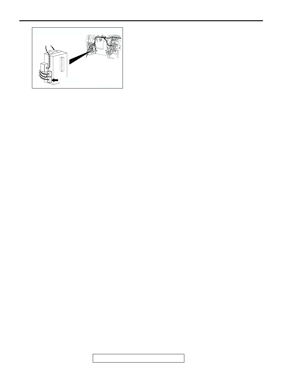
AC204174

CONNECTOR : D-224

D-224(B)

AG

SYMPTOM PROCEDURES

TSB Revision

SWS SYMPTOM PROCEDURES

54Bb-292

DIAGNOSIS

Required Special Tools:

• MB991223: Harness Set

• MB991502: Scan Tool (MUT-II)

• MB991862: SWS monitor kit

STEP 1. Use scan tool MB991502 to select "ECU COMM 
CHK" on the SWS monitor display.
Check the ETACS-ECU.

CAUTION

To prevent damage to scan tool MB991502, always turn the 
ignition switch to the "LOCK" (OFF) position before con-
necting or disconnecting scan tool MB991502.
(1) Connect scan tool MB991502 to the data link connector 

(16-pin).

(2) Connect SWS monitor kit MB991862 to the data link 

connector (13-pin).

(3) When the ignition switch is turned to the "ON" position.
(4) Operate scan tool MB991502 according to the procedure 

below to display "ECU COMM CHK."

1. Select "SYSTEM SELECT."
2. Select "SWS."
3. Select "SWS MONITOR."
4. Select "ECU COMM CHK."

(5) Scan tool MB991502 should show "OK" on the "ECU 

COMM CHK" menu for the "ETACS ECU" menu.

Q: Is "OK" displayed on the "ETACS ECU" menu?

YES : Go to Step 2.
NO :  Refer to Inspection Procedure A-3 "Communication 

with ETACS-ECU is not possibl

P.54Bb-25

."

AC204222AB

16-pin

13-pin

MB991502

MB991862

SYMPTOM PROCEDURES

TSB Revision

SWS SYMPTOM PROCEDURES

54Bb-293

STEP 2. Check the input signal by using "DATA LIST" 
menu of the SWS monitor.
Turn the ignition switch to the "ON" position before checking 
input signals from the ignition switch (IG1).
Operate scan tool MB991502 according to the procedure below 
to display "ETACS ECU." 

1. Select "SYSTEM SELECT."
2. Select "SWS."
3. Select "SWS MONITOR."
4. Select "DATA LIST."
5. Select "ETACS ECU."

Check that normal conditions are displayed on the items 
described in the table below.

Q: Is normal condition displayed "IG SW (IG1)"?

YES : Go to Step 3.
NO :  Refer to Inspection Procedure O-2 "ETACS-ECU 

does not receive any signal from the ignition switch 
(IG1) 

P.54Bc-7

."

STEP 3. Check the input signal (by using the pulse check 
mode of the monitor.)
Check input signal from the driver's side seat belt switch.
Operate scan tool MB991502 according to the procedure below 
to display "PULSE CHECK."

1. Select "SYSTEM SELECT."
2. Select "SWS."
3. Select "PULSE CHECK."

• When the driver's seat belt is fastened, check if scan tool 

MB991502 sounds or not.

Q: Does scan tool MB991502 sound when the driver's side 

seat belt is fastened?
Yes :  
Go to Step 4.
No :  Refer to Inspection Procedure P-3 "ETACS-ECU does 

not receive any signal from the driver's side seat belt 
switch 

P.54Bc-57

."

ITEM NO.

ITEM NAME

NORMAL CONDITION

ITEM 30

IG SW (IG1)

ON

AC204222AB

16-pin

13-pin

MB991502

MB991862

AC204222AB

16-pin

13-pin

MB991502

MB991862

SYMPTOM PROCEDURES

TSB Revision

SWS SYMPTOM PROCEDURES

54Bb-294

STEP 4. Check at ETACS-ECU connector D-224 in order to 
check the ground circuit to the seat belt warning light.
(1) Disconnect ETACS-ECU connector D-224, and measure at 

the wiring harness side. 

(2) Turn the ignition switch to the "ON" position.

(3) Connect terminal 39 to ground.
Q: Does the seat belt warning light illuminate?

YES : Replace the ETACS-ECU. Verify that the seat belt 

warning light illuminates normally.

NO :  Go to Step 5.

STEP 5. Check the seat belt warning light bulb.
Q: Is the seat belt warning light bulb in good condition?

YES : Go to Step 6.
NO :  Replace the bulb. Verify that the seat belt warning 

light illuminates normally.

STEP 6. Check the combination meter (printed-circuit 
board).
(1) Remove the combination meter.
(2) Remove the seat belt warning light bulb. Then measure the 

resistance value between the bulb terminals.

(3) Install the bulb to the combination meter, and then measure 

the resistance value between connector D-04 terminal 32 
and connector D-03 terminal 62. The measured resistance 
value should be roughly the same as the value measured in 
Step (2). 

Q: Are these two resistance values extremely different?

YES : Repair or replace the combination meter (printed 

circuit board). Verify that the seat belt warning light 
illuminates normally. 

NO (much the same) : Go to Step 7.

AC204174

CONNECTOR : D-224

AD

D-224(B)

D-224(B)

HARNESS SIDE

21

23

24

22

32

3433

31

26

27

28

3029

38

39

40

36

37

25

35

21

22

23

24

25

26

27

28

29

30

31

32

33

34

35

36

37

38

39

40

ACX01582AB

CONNECTOR D-224
(HARNESS SIDE)

ACX02344 AB

SEAT BELT WARNING LIGHT

66

65

64

63

62

61

52

51

59

67

58

57

56

55

54

53

60

46

45

44

43

42

41

32

31

39

47

38

37

36

35

34

33

40

ACX02366

CONNECTOR D-03

CONNECTOR D-04

AB


Content   ..  309  310  311  312   ..