Mitsubishi Montero (2002-2004). Manual - part 298


  Index      Mitsubishi     Mitsubishi Montero - service repair manual 2002-2004 year


Search            


Content   ..  296  297  298  299   ..


Mitsubishi Montero (2002-2004). Manual - part 298


SYMPTOM PROCEDURES

TSB Revision

SWS SYMPTOM PROCEDURES

54Bb-239

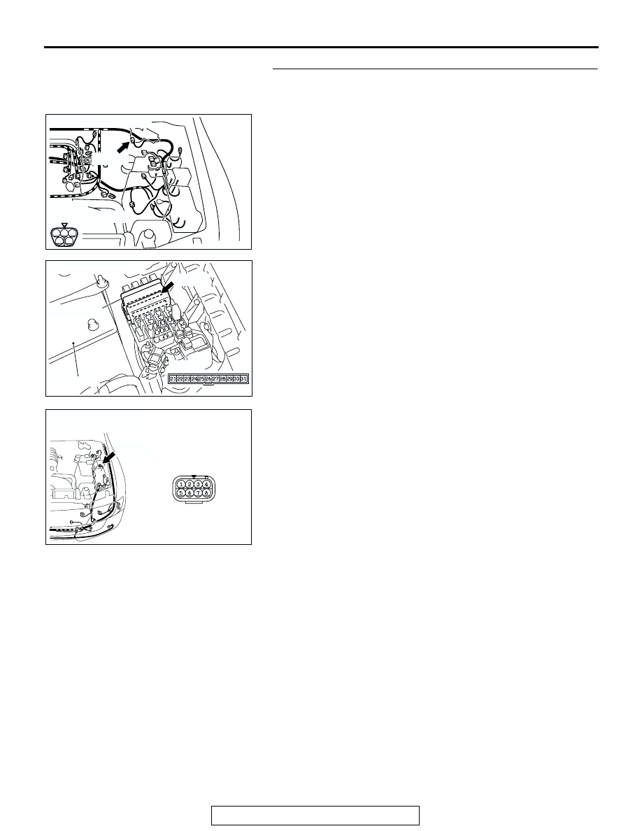
STEP 11. Check the wiring harness between windshield 
wiper motor connector B-12 (terminal 1) and front-ECU 
connector A-08X (terminal 28).

NOTE: Also check intermediate connector A-05 for loose, cor-
roded, or damaged terminals, or terminals pushed back in the 
connector. If intermediate connector A-05 is damaged, repair or 
replace the damaged component(s) as described in GROUP 
00E, Harness Connector Inspection 

P.00E-2

.

Q: Is the wiring harness between windshield wiper motor 

connector B-12 (terminal 1) and front-ECU connector A-
08X (terminal 28) in good condition?
YES : 
Go to Step 12.
NO :  The wiring harness may be damaged or the 

connector(s) may have loose, corroded or damaged 
terminals, or terminals pushed back in the connector. 
Repair the wiring harness as necessary. Verify that 
the windshield wiper operates normally when the 
windshield wiper switch is moved to each position.

AC205116 AD

CONNECTOR: B-12

B-12 (B)

(HARNESS SIDE)

B-12 (B)

1

2

3

4

5

AC205138

CONNECTOR: A-08X

AC

BATTERY

FRONT-ECU

A-08X

A-08X

AC205142AC

CONNECTOR: A-05

A-05(B)

A-05(B)

SYMPTOM PROCEDURES

TSB Revision

SWS SYMPTOM PROCEDURES

54Bb-240

STEP 12. Check the wiring harness between windshield 
wiper motor connector B-12 (terminal 4) and front-ECU 
connector A-08X (terminal 27).
Q: Is the wiring harness between windshield wiper motor 

connector B-12 (terminal 4) and front-ECU connector A-
08X (terminal 27) in good condition?
YES : 
No action is necessary and testing is complete.
NO :  The wiring harness may be damaged or the 

connector(s) may have loose, corroded or damaged 
terminals, or terminals pushed back in the connector. 
Repair the wiring harness as necessary. Verify that 
the windshield wiper operates normally when the 
windshield wiper switch is moved to each position.

AC205116 AD

CONNECTOR: B-12

B-12 (B)

(HARNESS SIDE)

B-12 (B)

1

2

3

4

5

AC205138

CONNECTOR: A-08X

AC

BATTERY

FRONT-ECU

A-08X

A-08X

SYMPTOM PROCEDURES

TSB Revision

SWS SYMPTOM PROCEDURES

54Bb-241

INSPECTION PROCEDURE G-2: Windshield Wiper and Washer: The windshield wipers do not work 
when the windshield wiper switch is at "INT" or "MIST" position or the windshield washer switch is at 
"ON" position. However, the wipers work at low speed when the windshield wiper switch is at "LO" or 
"HI."

NOTE: This troubleshooting procedure requires the 
use of scan tool MB991502 and SWS monitor kit 
MB991862. For details on how to use the SWS mon-
itor, refer to "How to use SWS monitor 

P.54Ba-8

."

.

TECHNICAL DESCRIPTION (COMMENT)
The system may be at fail-safe mode as the SWS 
communication line is defective.
If the system can not receive any signal from the col-
umn switch (windshield wiper and washer switch) 
due to a open circuit in the SWS communication line 
or other reasons, the system will enter the fail-safe 
mode when the ignition switch is at the "ACC" posi-
tion.

.

TROUBLESHOOTING HINTS

• The column switch (windshield wiper and washer 

switch) may be defective

• The front-ECU may be defective

• The wiring harness or connectors may have 

loose, corroded, or damaged terminals, or termi-
nals pushed back in the connector

Windshield Wiper Motor Drive Circuit

SYMPTOM PROCEDURES

TSB Revision

SWS SYMPTOM PROCEDURES

54Bb-242

DIAGNOSIS

Required Special Tools:

• MB991223: Harness Set

• MB991502: Scan Tool (MUT-II) 

• MB991862: SWS Monitor Kit

 Use scan tool MB991502 to select "ECU COMM CHK" on 
the SWS monitor display.
Check the following ECUs:

• Column-ECU

• Front-ECU

CAUTION

To prevent damage to scan tool MB991502, always turn the 
ignition switch to the "LOCK" (OFF) position before con-
necting or disconnecting scan tool MB991502. 
(1) Connect scan tool MB991502 to the data link connector 

(16-pin).

(2) Connect SWS monitor kit MB991862 to the data link 

connector (13-pin).

(3) Turn the ignition switch to the "ON" position.
(4) Operate scan tool MB991502 according to the procedure 

below to display "ECU COMM CHECK."

1. Select "SYSTEM SELECT."
2. Select "SWS."
3. Select "SWS MONITOR."
4. Select "ECU COMM CHK".

(5) Scan tool MB991502 should show "OK" on the "ECU 

COMM CHK" menus for both the "COLUMN ECU" and the 
"FRONT ECU" menus.

Q: Is "OK" displayed on the "COLUMN ECU" and "FRONT 

ECU" menu?
"OK" is displayed for all the items : 
Replace the front-

ECU. Verify that the windshield wiper works normally.

"NG" is displayed on the "COLUMN ECU" menu : Refer 

to Inspection Procedure A-2 "Communication with 
column switch (column-ECU) is not possible

P.54Bb-

16

."

"NG" is displayed on the "FRONT ECU" menu : Refer to 

Inspection procedure A-4 "Communication with front-
ECU is not possible

P.54Bb-32

."

AC204222AB

16-pin

13-pin

MB991502

MB991862


Content   ..  296  297  298  299   ..