Mitsubishi Montero (2002-2004). Manual - part 245
SYMPTOM PROCEDURES
TSB Revision
SWS SYMPTOM PROCEDURES
54Bb-27
DIAGNOSIS
Required Special Tools:
• MB991223: Harness Set
• MB991502: Scan Tool (MUT-II)
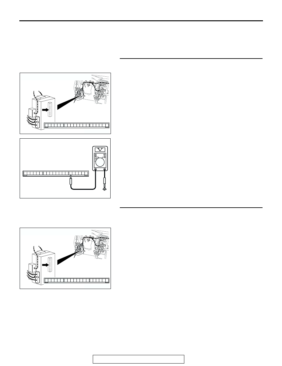
STEP 1. Check the battery power supply circuit to the
ETACS-ECU. Test at ETACS-ECU connector D-222.
(1) Disconnect ETACS-ECU connector D-222 and measure the
voltage available at the junction block side of the connector.
(2) Measure the voltage between terminal 6 and ground.
• The voltage should be approximately 12 volts (battery
positive voltage).
Q: Is the measured voltage approximately 12 volts (battery
positive voltage)?
YES : Go to Step 4.
NO : Go to Step 2.
STEP 2. Check ETACS-ECU connector D-222 for loose,
corroded or damaged terminals, or terminals pushed back
in the connector.
Q: Is ETACS-ECU connector D-222 in good condition?
YES : Go to Step 3.
NO : Repair or replace the damaged component(s). Refer
to GROUP 00E, Harness Connector Inspection
. The system should communicate with the
ETACS-ECU normally.
AC204174
CONNECTOR : D-222
AB
1
2
3
5
6
4
9 8
121110
13
15 14
16
17
7
19
20
18
JUNCTION BLOCK SIDE
D-222
ACX01610
19
20
1817 1615 141312 1110 9 8 7
6 5 4 3 2 1
AB
CONNECTOR D-222
(JUNCTION BLOCK SIDE)
AC204174
CONNECTOR : D-222
AB
1
2
3
5
6
4
9 8
121110
13
15 14
16
17
7
19
20
18
JUNCTION BLOCK SIDE
D-222