Mitsubishi Montero (2002-2004). Manual - part 240


  Index      Mitsubishi     Mitsubishi Montero - service repair manual 2002-2004 year


Search            


Content   ..  238  239  240  241   ..


Mitsubishi Montero (2002-2004). Manual - part 240


SYMPTOM PROCEDURES

TSB Revision

SWS SYMPTOM PROCEDURES

54Bb-7

SYMPTOM PROCEDURES

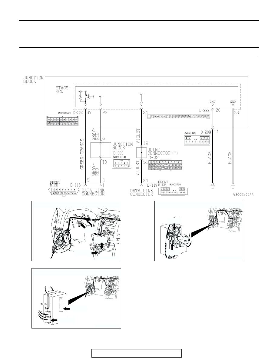
INSPECTION PROCEDURE A-1: Communication with the SWS monitor kit is not possible.

.

Scan Tool Communication and ETACS-ECU Ground Circuit

AC204170

CONNECTORS : D-02, D-117, D-118

BH

D-118(B)

D-02

D-117

AC204173

CONNECTORS : D-209, D-220

D-208

D-220

AT

AC204174

CONNECTORS : D-222, D-224

D-224(B)

AH

D-222

SYMPTOM PROCEDURES

TSB Revision

SWS SYMPTOM PROCEDURES

54Bb-8

TECHNICAL DESCRIPTION (COMMENT)
The SWS monitor kit may be connected improperly.

.

TROUBLESHOOTING HINTS

• The SWS monitor body (I/F cartridge) may be 

defective

• The SWS monitor harness may be defective

• The ETACS-ECU may be defective

• The wiring harness or connectors may have 

loose, corroded, or damaged terminals, or termi-
nals pushed back in the connector

DIAGNOSIS

Required Special Tools:

• MB991223: Harness Set

• MB991502: Scan Tool (MUT-II) 

STEP 1. Verify SWS monitor kit MB991862 for proper 
connection.
Q: Is SWS monitor kit MB991862 connected with the 

column switch properly?
YES : 
Go to Step 2.
NO :  Connect SWS monitor kit MB991862 to the column 

switch securely.

STEP 2. Verify the power supply circuit to the ETACS-ECU.
Q: Does the system communicate with scan tool 

MB991502 when the ignition switch is turned to the 
"ON" position?
YES : 
Go to Step 3.
NO :  Refer to Inspection Procedure A-3 "Communication 

with the ETACS-ECU is not possible 

P.54Bb-25

."

SYMPTOM PROCEDURES

TSB Revision

SWS SYMPTOM PROCEDURES

54Bb-9

STEP 3. Check the ground circuit to the ETACS-ECU. Test 
at ETACS-ECU connector D-222 and D-224.
(1) Disconnect ETACS-ECU connector D-222 and D-224, and 

measure the resistance available at the junction block side 
of the connector.

(2) Measure the resistance value between ETACS-ECU 

connector D-222 terminal 20 and ground, and also between 
ETACS-ECU connector D-224 terminal 23 and ground.

• The resistance should equal 2 ohms or less.

Q: Is the measured resistance 2 ohms or less?

YES : Go to Step 6.
NO :  Go to Step 4.

AC204192

CONNECTORS : D-222, D-224

D-222

AC

HARNESS SIDE

D-224(B)

D-222

D-224(B)

1

2

3

5

6

4

9 8

121110

13

15 14

16

17

7

19

20

18

JUNCTION BLOCK SIDE

21

23

24

22

32

3433

31

26

27

28

3029

38

39

40

36

37

25

35

ACX01569

19

20

1817 1615 141312 1110 9 8 7

6 5 4 3 2 1

AB

CONNECTOR D-222
(JUNCTION BLOCK SIDE)

AC204759

21

23

24

22

32

3433

31

26

27

28

3029

38

39

40

36

37

25

35

AB

CONNECTOR D-224
(HARNESS SIDE)

SYMPTOM PROCEDURES

TSB Revision

SWS SYMPTOM PROCEDURES

54Bb-10

STEP 4. Check ETACS-ECU connector D-222 and D-224 for 
loose, corroded or damaged terminals, or terminals 
pushed back in the connector.
Q: Are ETACS-ECU connector D-222 and D-224 in good 

condition?
YES : 
Go to Step 5.
NO :  Repair or replace the damaged component(s). Refer 

to GROUP 00E, Harness Connector Inspection 

P.00E-2

. The system should communicate with the 

SWS monitor normally.

AC204192

CONNECTORS : D-222, D-224

D-222

AC

HARNESS SIDE

D-224(B)

D-222

D-224(B)

1

2

3

5

6

4

9 8

121110

13

15 14

16

17

7

19

20

18

JUNCTION BLOCK SIDE

21

23

24

22

32

3433

31

26

27

28

3029

38

39

40

36

37

25

35


Content   ..  238  239  240  241   ..