Mitsubishi Montero (2002-2004). Manual - part 1104


  Index      Mitsubishi     Mitsubishi Montero - service repair manual 2002-2004 year


Search            


Content   ..  1102  1103  1104  1105   ..


Mitsubishi Montero (2002-2004). Manual - part 1104


M-ASTC DIAGNOSIS

TSB Revision

MITSUBISHI ACTIVE SKID AND TRACTION CONTROL SYSTEM

35C-33

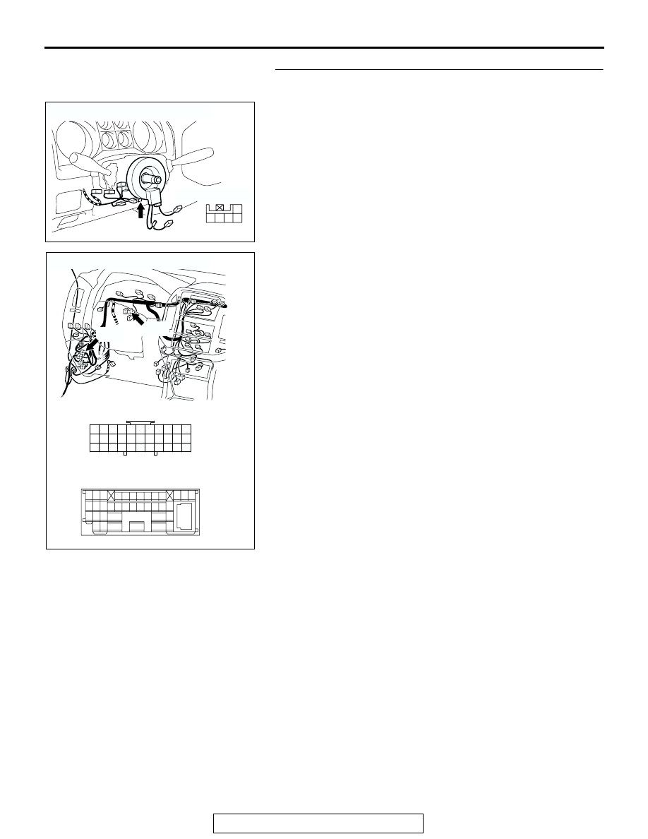
STEP 4. Check the wiring harness between steering wheel 
sensor connector D-225 terminal 1 and fusible link No.1.

NOTE: Also check joint connector D-02 and intermediate con-
nector D-28 for loose, corroded, or damaged terminals, or ter-
minals pushed back in the connectors. If joint connector D-02 
or intermediate connector D-28 are damaged, repair or replace 
the damaged component(s) as described in GROUP 00E, Har-
ness Connector Inspection 

P.00E-2

. If the connector has been 

repaired or replaced, go to Step 12.
Q: Is the wiring harness between steering wheel sensor 

connector D-225 terminal 1 and the fusible link No.1 in 
good condition?
YES : 
Go to Step 12.
NO :  Repair the wiring harness, and then go to Step 12.

AC204172

CONNECTOR: D-225

HARNESS SIDE

AD

3 2

1

4

5

AC204188

CONNECTORS: D-02, D-28

D-02

D-02

D-28

AB

D-28

9 10

8

6 7

31 32

30

29

18 19 20 21

5

4

2

1

3

27

26

24

23

25

12 13 14 15 16 17

28

11
22
33

2 3

27

32

28

33

16

15

4 5

19

18

29

17

34

7 8

35

22

21

9 10

30

36

31

37

25

24

23

6

20

1

14

26

11

13

12

38

M-ASTC DIAGNOSIS

TSB Revision

MITSUBISHI ACTIVE SKID AND TRACTION CONTROL SYSTEM

35C-34

STEP 5. Check the battery power supply to the steering 
wheel sensor. Measure at steering wheel sensor connector 
D-225.
(1) Disconnect steering wheel sensor connector D-225, and 

measure the voltage at the harness-side connector.

(2) Turn the ignition switch to the "ON" position.

(3) Measure the voltage between steering wheel sensor 

connector D-225 terminal 2 and body ground.

• The voltage should measure battery voltage (approxi-

mately 12 volts).

Q: Does the voltage measure battery voltage 

(approximately 12 volts)?
YES : 
Go to Step 8.
NO :  Go to Step 6.

STEP 6. Check steering wheel sensor connector D-225.
Q: Is steering wheel sensor connector D-225 in good 

condition?
YES : 
Go to Step 7.
NO :  Repair or replace the connector, and then go to Step 

12.

AC204172

CONNECTOR: D-225

HARNESS SIDE

AD

3 2

1

4

5

AC204580

3 2

1

4

5

HARNESS SIDE: D-225

AS

AC204172

CONNECTOR: D-225

HARNESS SIDE

AD

3 2

1

4

5

M-ASTC DIAGNOSIS

TSB Revision

MITSUBISHI ACTIVE SKID AND TRACTION CONTROL SYSTEM

35C-35

STEP 7. Check the wiring harness between steering wheel 
sensor connector D-225 terminal 2 and ignition switch 
(IG2).

NOTE: Also check joint connector D-01 and junction block con-
nector D-208 and D-210 for loose, corroded, or damaged termi-
nals, or terminals pushed back in the connectors. If joint 
connector D-01 or junction block connector D-208 or D-210 are 
damaged, repair or replace the damaged component(s) as 
described in GROUP 00E, Harness Connector Inspection 

P.00E-2

. If the connector has been repaired or replaced, go to 

Step 12.
Q: Is the wiring harness between steering wheel sensor 

connector D-225 terminal 2 and the ignition switch (IG2) 
in good condition?
YES : 
Go to Step 12.
NO :  Repair the wiring harness, and then go to Step 12.

AC204172

CONNECTOR: D-225

HARNESS SIDE

AD

3 2

1

4

5

AC204170

CONNECTOR: D-01

AB

9 10

8

6 7

31 32

30

29

18 19 20 21

5

4

2

1

3

27

26

24

23

25

12 13 14 15 16 17

28

11
22
33

AC204191

CONNECTORS: D-208, D-210

D-208

AC

HARNESS SIDE

HARNESS SIDE

D-210

D-208

D-210

1

2

3

5

6

4

1

2

7 6

3

9

4

11

12

10

13

5

8

M-ASTC DIAGNOSIS

TSB Revision

MITSUBISHI ACTIVE SKID AND TRACTION CONTROL SYSTEM

35C-36

STEP 8. Check the steering wheel sensor for ground 
circuit. Measure at steering wheel sensor connector D-225.
(1) Disconnect steering wheel sensor connector D-225, and 

measure the resistance at the harness-side connector.

(2) Measure the resistance between steering wheel sensor 

connector D-225 terminal 5 and body ground.

• The resistance should measure 2 ohms or less.

Q: Does the resistance measure 2 ohms or less?

YES : Go to Step 11.
NO :  Go to Step 9.

STEP 9. Check steering wheel sensor connector D-225.
Q: Is steering wheel sensor connector D-225 in good 

condition?
YES : 
Go to Step 10.
NO :  Repair or replace the connector, and then go to Step 

12.

STEP 10. Check the wiring harness between steering 
wheel sensor connector D-225 terminal 5 and the body 
ground.
Q: Is the wiring harness between steering wheel sensor 

connector D-225 terminal 5 and the body ground in 
good condition?
YES : 
Go to Step 12.
NO :  Repair the wiring harness, and then go to Step 12.

AC204172

CONNECTOR: D-225

HARNESS SIDE

AD

3 2

1

4

5

AC204581

3 2

1

4

5

HARNESS SIDE: D-225

AV

AC204172

CONNECTOR: D-225

HARNESS SIDE

AD

3 2

1

4

5

AC204172

CONNECTOR: D-225

HARNESS SIDE

AD

3 2

1

4

5


Content   ..  1102  1103  1104  1105   ..