Mitsubishi Montero (2002-2004). Manual - part 1083


  Index      Mitsubishi     Mitsubishi Montero - service repair manual 2002-2004 year


Search            


Content   ..  1081  1082  1083  1084   ..


Mitsubishi Montero (2002-2004). Manual - part 1083


CHARGING SYSTEM

TSB Revision

ENGINE ELECTRICAL

16-5

SPECIAL TOOL

M1161000600022

ON-VEHICLE SERVICE

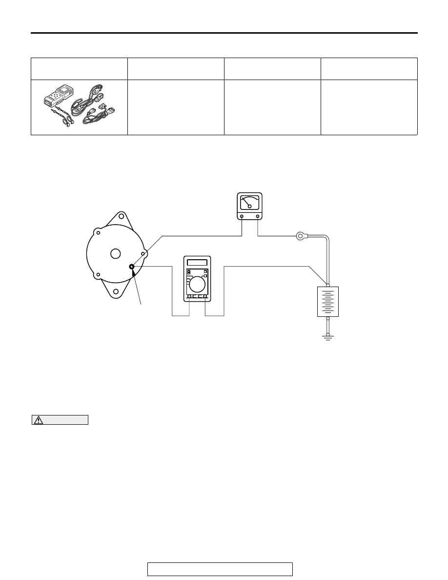
GENERATOR OUTPUT LINE VOLTAGE DROP TEST

M1161000900175

Required Special Tool:
MB991502: Scan Tool
This test determines whether the wiring from the 
generator "B" terminal to the positive battery terminal 
(including the fusible link) is in good condition or not:

WARNING

Battery posts, terminals and related acces-
sories contain lead and lead compounds. 
WASH HANDS AFTER HANDLING.

1. Always be sure to check the following before the 

test.

• Generator installation

• Generator drive belt tension (Refer to GROUP 

00, Maintenance Service 

− Drive belt

P.00-39

.)

• Fusible link

• Abnormal noise from the generator while the 

engine is running

2. Turn the ignition switch to the "OFF" position.

3. Disconnect the negative battery cable.
4. Disconnect the generator output wire from the 

generator "B" terminal and connect a DC test 
ammeter with a range of 0 

− 100 A in series 

between the "B" terminal and the disconnected 
output wire. (Connect the positive lead of the 
ammeter to the "B" terminal, and then connect the 
negative lead of the ammeter to the disconnected 
output wire.)
NOTE: A clamp-type ammeter which enables 
measurements to be taken without disconnecting 
the generator output wire is recommended. If the 
voltage may have dropped due to a bad connec-
tion at generator "B" and the generator "B" termi-
nal is loosened when the test ammeter is 
connected, the connection will be completed at 
this time and the possibility of finding problems 
will be reduced.

TOOL

TOOL NUMBER AND 
NAME

SUPERSESSION

APPLICATION

MB991502
Scan tool (MUT-II)

MB991496-OD

Checking of engine idle 
speed

B991502

AKX00185

GENERATOR

AMMETER

VOLTMETER
(DIGITAL-TYPE)

BATTERY

+

"B"TERMINAL

AB

CHARGING SYSTEM

TSB Revision

ENGINE ELECTRICAL

16-6

5. Connect a digital-type voltmeter between the 

generator "B" terminal and the positive battery 
terminal. (Connect the positive lead of the 
voltmeter to the "B" terminal, and then connect the 
negative lead of the voltmeter to the positive 
battery cable.)

6. Reconnect the negative battery cable.
7. Connect a tachometer or scan tool MB991502.
8. Leave the hood open.
9. Start the engine.
10.With the engine running at 2,500 r/min, turn the 

headlights and other lights on and off to adjust the 
generator load so that the value displayed on the 
ammeter is slightly above 30 A.

Limit value: maximum 0.3 V 

NOTE: When the generator output is high and the 
value displayed on the ammeter does not 
decrease to 30 A, set the value to 40 A. Read the 
value displayed on the voltmeter at this time.
In this case the limit value becomes maximum 0.4 
V. Adjust the engine speed by gradually decreas-
ing it until the value displayed on the ammeter is 
30 A. Take a reading of the value displayed on the 
voltmeter at this time.

11.If the value displayed on the voltmeter is above 

the limit value, there is probably a malfunction in 
the generator output wire, Check the wiring 
between the generator "B" terminal and the 
positive battery terminal (including fusible link). If 
a terminal is not sufficiently tight or if the harness 
has become discolored due to overheating, repair 
and then test again.

12.After the test, run the engine at idle. 
13.Turn off all lights and turn the ignition switch to the 

"LOCK" (OFF) position.

14.Disconnect the tachometer or scan tool 

MB991502.

15.Disconnect the negative battery cable.
16.Disconnect the ammeter and voltmeter and 

tachometer.

17.Connect the generator output wire to the 

generator "B" terminal.

18.Connect the negative battery cable.

OUTPUT CURRENT TEST

M1161001000164

Required Special Tool:
MB991502: Scan Tool (MUT-II)
This test determines whether the generator outputs 

normal current.

WARNING

Battery posts, terminals and related acces-
sories contain lead and lead compounds. 
WASH HANDS AFTER HANDLING.

1. Before the test, always be sure to check the 

following.

AKX00186

GENERATOR

AMMETER

VOLTMETER

BATTERY

+

-

IGNITION
SWITCH

CHARGING INDICATOR

BRAKE WARNING LIGHT

L

S

B

LOAD

AB

CHARGING SYSTEM

TSB Revision

ENGINE ELECTRICAL

16-7

• Generator installation

• Battery (Refer to GROUP 54A, Battery − On-

vehicle Service 

− Battery Check 

P.54A-4

.)

NOTE: The battery to be used should be slightly 
discharged. The load in a fully-charged battery 
will be insufficient and the test may not be able to 
be carried out correctly.

• Generator drive belt tension (Refer to GROUP 

00, Maintenance Service 

− Drive Belts 

P.00-39

.)

• Fusible link

• Abnormal noise from the generator while the 

engine is running

2. Turn the ignition switch to the "LOCK" (OFF) 

position.

3. Disconnect the negative battery cable.

WARNING

Never use clips to connect the line. Loose 
connections (e.g. using clips) will lead to a 
serious accident because of high current.

4. Disconnect the generator output wire from the 

generator "B" terminal and connect a DC test 
ammeter with a range of 0 

− 100 A in series 

between the "B" terminal and the disconnected 
output wire. (Connect the positive lead of the 
ammeter to the "B" terminal, and then connect the 
negative lead of the ammeter to the disconnected 
output wire.)
NOTE: A clamp-type ammeter which enables 
measurements to be taken without disconnecting 
the generator output wire is recommended.

5. Connect a voltmeter with a range of 0 

− 20 V 

between the generator "B" terminal and the 
ground. (Connect the positive lead of the 
voltmeter to the "B" terminal, and then connect the 
negative lead of the voltmeter to the ground.)

6. Connect the negative battery cable.
7. Connect a tachometer or scan tool MB991502.
8. Leave the hood open.
9. Check to be sure that the reading on the voltmeter 

is equal to the battery positive voltage.
NOTE: If the voltage is 0 V, the cause is probably 
an open circuit in the wire or fusible link between 
the generator "B" terminal and the battery positive 
terminal.

10.After turning the light switch on and turning on the 

headlights, start the engine.
NOTE: Because the current from the battery will 
soon drop after the engine is started, step11 
should be carried out as quickly as possible in 
order to obtain the maximum current output value.

11.Immediately after setting the headlights to high 

beam and turning the heater blower switch to the 
high revolution position, increase the engine 
speed to 2,500 r/min and read the maximum 
current output value displayed on the ammeter.

Limit value: 70 % of nominal current output

NOTE: For the nominal current output, refer to the 
Generator Specifications
NOTE: The current output value will depend on 
the electrical load and the temperature of the gen-
erator body.
NOTE: If the electrical load is small while testing, 
the specified level of current may not be output 
even though the generator is normal. In such 
cases, increase the electrical load by leaving the 
headlights turned on for some time to discharge 
the battery.
NOTE: The specified level of current also may not 
be output if the temperature of the generator body 
or the ambient temperature is too high. In such 
cases, cool the generator and then test again.

12.The reading on the ammeter should be above the 

limit value. If the reading is below the limit value 
and the generator output wire is normal, remove 
the generator from the engine and check the 
generator.

13.Run the engine at idle speed after the test.
14.Turn the ignition switch to the "LOCK" (OFF) 

position.

15.Disconnect the tachometer or scan tool 

MB991502.

16.Disconnect the negative battery cable.
17.Disconnect the ammeter and voltmeter and 

tachometer.

18.Connect the generator output wire to the 

generator "B" terminal.

19.Connect the negative battery cable.

CHARGING SYSTEM

TSB Revision

ENGINE ELECTRICAL

16-8

REGULATED VOLTAGE TEST

M1161001100172

Required Special Tool:
MB991502: Scan Tool (MUT-II)
This test determines whether the voltage regulator is 
correctly controlling the generator output voltage.

WARNING

Battery posts, terminals and related acces-
sories contain lead and lead compounds. 
WASH HANDS AFTER HANDLING.

1. Always be sure to check the following before the 

test:

• Generator installation

• Check to be sure that the battery installed in the 

vehicle is fully charged (Refer to GROUP 54A, 
Battery 

− On-vehicle Service − Battery Check 

P.54A-4

.)

• Generator drive belt tension (Refer to GROUP 

00, Maintenance Service 

− Drive Belts 

P.00-39

.)

• Fusible link

• Abnormal noise from the generator while the 

engine is running

2. Turn the ignition switch to the "LOCK" (OFF) 

position.

3. Disconnect the negative battery cable.
4. Connect a digital-type voltmeter between the 

generator "S" terminal and the ground. (Connect 
the positive lead of the voltmeter to the "S" 
terminal, and then connect the negative lead of 
the voltmeter to a secure ground or to the battery 
negative terminal.)

5. Disconnect the generator output wire from the 

generator "B" terminal.

6. Connect a DC test ammeter with a range of 0 

− 

100 A in series between the "B" terminal and the 
disconnected output wire. (Connect the positive 
load of the ammeter to the "B" terminal, and then 
connect the negative lead of the ammeter to the 
disconnected output wire.)

7. Reconnect the negative battery cable.
8. Connect a tachometer or the scan tool 

MB991502.

9. Turn the ignition switch to the "ON" position and 

check that the reading on the voltmeter is equal to 
the battery positive voltage.
NOTE:  If the voltage is 0 V, the cause is probably 
an open circuit in the wire or fusible link between 
the generator "S" terminal and the battery positive 
terminal.

10.Check to be sure that all lights and accessories 

are off.

11.Start the engine.
12.Increase the engine speed to 2,500 r/min.
13.Read the value displayed on the voltmeter when 

the current output by the generator becomes 10 A 
or less.

14.If the voltage reading conforms to the value in the 

voltage regulation table, then the voltage regulator 
is operating normally.
If the voltage is outside the standard value, there 
is a malfunction of the voltage regulator or the 
generator (Refer to the following table).

AKX00187

IGNITION
SWITCH(IG1) CHARGING INDICATOR

BRAKE WARNING LIGHT

GENERATOR

AMMETER

VOLTMETER
(DIGITAL-TYPE)

LOAD

L

S

B

BATTERY

+

-

AB


Content   ..  1081  1082  1083  1084   ..