Mitsubishi Montero (2002-2004). Manual - part 1053


  Index      Mitsubishi     Mitsubishi Montero - service repair manual 2002-2004 year


Search            


Content   ..  1051  1052  1053  1054   ..


Mitsubishi Montero (2002-2004). Manual - part 1053


ANTI-LOCK BRAKING SYSTEM (ABS) DIAGNOSIS

TSB Revision

ANTI-LOCK BRAKING SYSTEM (ABS)

35B-83

DIAGNOSIS

Required Special Tool:

• MB991223: Harness Set

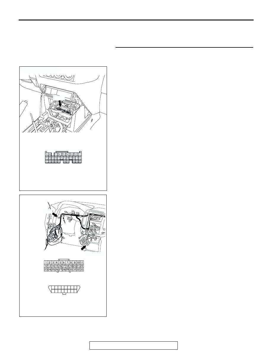
STEP 1. Check the harness wires between M-ASTC-ECU 
connector E-119 terminal 21 and data link connector D-118 
terminal 7.
NOTE: After inspecting M-ASTC-ECU connector E-119, joint connec-
tor D-116, intermediate connector E-111 and joint connector D-29, 
inspect the wire. If M-ASTC-ECU connector E-119, joint connector D-
116, intermediate connector E-111 and joint connector D-29 are dam-
aged, repair or replace them. Refer to GROUP 00E, Harness Con-
nector Inspection 

P.00E-2

. If the connector has been repaired or 

replaced, go to Step 5.
Q: Are the harness wires between M-ASTC-ECU connector E-119 

terminal 21 and data link connector D-118 terminal 7 
damaged?
YES :  
Repair them and then go to Step 5.
NO :  Go to Step 2.

AC203901

AC204627AC

CONNECTOR: E-119

E-119

HARNESS CONNECTOR: 
COMPONENT SIDE

E-119

AC204677

AC204701AD

CONNECTORS: D-29, D-118

D-29

D-29

DATA LINK CONNECTOR:

FRONT SIDE

8

16

15

7

5

1314

6

12

4

2

1011

3

9

1

D-118(B)

D-118

ANTI-LOCK BRAKING SYSTEM (ABS) DIAGNOSIS

TSB Revision

ANTI-LOCK BRAKING SYSTEM (ABS)

35B-84

STEP 2. Check the power supply circuit at M-ASTC-ECU 
connectors E-119 and E-120.
(1) Disconnect connectors E-119 and E-120, and measure at the 

harness side.

(2) Turn the ignition switch to the "ON" position.

(3) Measure the voltage between M-ASTC-ECU connector E-120 

terminal 63 and ground. It should be approximately 12 volts 
(battery positive voltage).

Q: Is voltage approximately 12 volts (battery positive voltage)? 

YES :  Go to Step 4.
NO :  Go to Step 3.

AC203901

AC204627AO

E-119

CONNECTORS: E-119, E-120

E-119

HARNESS CONNECTOR:
COMPONENT SIDE

E-120

HARNESS CONNECTOR:
COMPONENT SIDE

E-120

AC204708AB

HARNESS CONNECTOR: 
COMPONENT SIDE

E-120

HARNESS CONNECTOR:
COMPONENT SIDE

E-119

ANTI-LOCK BRAKING SYSTEM (ABS) DIAGNOSIS

TSB Revision

ANTI-LOCK BRAKING SYSTEM (ABS)

35B-85

STEP 3. Check the harness wire between ignition switch (IG2) 
connector D-204 terminal 4 and M-ASTC-ECU connectors E-119 
terminal 9 and E-120 terminal 63.

AC204709

CONNECTOR: D-204

D-204

AB

AC203901

AC204627AO

E-119

CONNECTORS: E-119, E-120

E-119

HARNESS CONNECTOR:
COMPONENT SIDE

E-120

HARNESS CONNECTOR:
COMPONENT SIDE

E-120

ANTI-LOCK BRAKING SYSTEM (ABS) DIAGNOSIS

TSB Revision

ANTI-LOCK BRAKING SYSTEM (ABS)

35B-86

NOTE: 

After inspecting M-ASTC-ECU connectors E-119 and E-120, 

intermediate connector E-111, joint connector D-116, junction block 
connector D-208 and D-212, inspect the wire. If M-ASTC-ECU con-
nectors E-119 and E-120, intermediate connector E-111, joint connec-
tor D-116, junction block connector D-208 and D-212 are damaged, 
repair or replace them. Refer to GROUP 00E, Harness Connector 
Inspection 

P.00E-2

If the connector has been repaired or replaced, 

go to Step 5.
Q: Are the harness wires between ignition switch (IG2) 

connector D-204 terminal 4 and M-ASTC-ECU connectors E-
119 terminal 9 and E-120 terminal 63 damaged?
YES :  
Repair them and then go to Step 5.
NO :  Go to Step 5.

AC204385

AC204673

CONNECTOR: E-111

AB

E-111

9

21

33

35

24

12

3 4

7

8

5 6

39

28

41

30

18

4243

31

1920

32

40

29

1617

38

27

15

37

36

26

14

13

25

2

1

34

23

11

10

22

E-111

AC204384

D-116

AE

CONNECTOR: D-116

AC204624 AF

CONNECTORS: D-208, D-212

D-208

JUNCTION BLOCK
(FRONT VIEW)

JUNCTION BLOCK CONNECTOR

D-212

D-212

D-208

6

2

5

1

7 8

11

4

9 10

3

JUNCTION BLOCK CONNECTOR


Content   ..  1051  1052  1053  1054   ..