Mitsubishi Montero (2002-2004). Manual - part 1049


  Index      Mitsubishi     Mitsubishi Montero - service repair manual 2002-2004 year


Search            


Content   ..  1047  1048  1049  1050   ..


Mitsubishi Montero (2002-2004). Manual - part 1049


ANTI-LOCK BRAKING SYSTEM (ABS) DIAGNOSIS

TSB Revision

ANTI-LOCK BRAKING SYSTEM (ABS)

35B-67

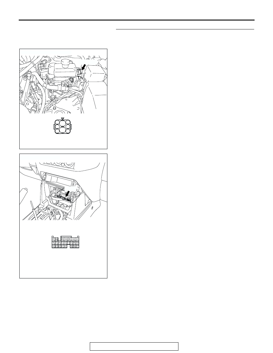
STEP 6. Check the harness wire between HBB connector 
B-17 terminal 3 and M-ASTC-ECU connector E-120 
terminal 55.
NOTE:  After inspecting HBB connector B-17, inspect the wire. 
If HBB connector B-17 is damaged, repair or replace it. Refer to 
GROUP 00E, Harness Connector Inspection 

P.00E-2

. If the 

connector has been repaired or replaced, go to Step 10.
Q: Is the harness wire between HBB connector B-17 

terminal 3 and M-ASTC-ECU connector E-120 terminal 
55 damaged?
YES : 
Repair it and then go to Step 10.
NO :  Go to Step 7.

AC204629 AE

CONNECTOR: B-17

B-17 (GR)

HARNESS CONNECTOR: 
COMPONENT SIDE

1

2

3

4

5

6

7

8

B-17

AC203901

AC204627AG

CONNECTOR: E-120

E-120

HARNESS CONNECTOR: 
COMPONENT SIDE

E-120

ANTI-LOCK BRAKING SYSTEM (ABS) DIAGNOSIS

TSB Revision

ANTI-LOCK BRAKING SYSTEM (ABS)

35B-68

STEP 7. Check the harness wire between fusible link 
number 31 and valve relay connector B-21X terminal 5.
NOTE:  After inspecting valve relay connector B-21X, inspect 
the wire. If valve relay connector B-21X is damaged, repair or 
replace it. Refer to GROUP 00E, Harness Connector Inspec-
tion 

P.00E-2

.

Q: Is the harness wire between fusible link number 31 and 

valve relay connector B-21X terminal 5 damaged?
YES : 
Repair it and then go to Step 10.
NO :  Go to Step 8.

ACX01501AF

FUSIBLE LINK 
No.31

BATTERY

FUSIBLE LINK No.31

AC204706

1

2

3

4

1

2

3

4

1

2

3

4

1

2

3

4

1

2

3

4

1

2

3

4

1

2

3

5

B-21X

CONNECTOR: B-21X

AB

RELAY BOX CONNECTOR

ANTI-LOCK BRAKING SYSTEM (ABS) DIAGNOSIS

TSB Revision

ANTI-LOCK BRAKING SYSTEM (ABS)

35B-69

STEP 8. Check the harness wire between valve relay 
connector B-21X terminal 2 and HBB connector B-18 
terminal 34.
NOTE:  After inspecting HBB connector B-18, inspect the wire. 
If HBB connector B-18 is damaged, repair or replace it. Refer to 
GROUP 00E, Harness Connector Inspection 

P.00E-2

. If the 

connector has been repaired or replaced, go to Step 10.
Q: Is the harness wire between valve relay connector B-

21X terminal 2 and HBB connector B-18 terminal 34 
damaged?
YES : 
Repair it and then go to Step 10.
NO :  Go to Step 9.

AC204626 AB

CONNECTOR: B-18

B-18 (B)

HARNESS CONNECTOR : 
COMPONENT SIDE

34

32

31

33

35

B-18

AC204706

1

2

3

4

1

2

3

4

1

2

3

4

1

2

3

4

1

2

3

4

1

2

3

4

1

2

3

5

B-21X

CONNECTOR: B-21X

AB

RELAY BOX CONNECTOR

ANTI-LOCK BRAKING SYSTEM (ABS) DIAGNOSIS

TSB Revision

ANTI-LOCK BRAKING SYSTEM (ABS)

35B-70

STEP 9. Check the HBB.
(1) Disconnect HBB connector B-17 and B-18, and measure at 

the HBB side.

(2) Check for continuity between HBB connector B-17 

terminals 3 and HBB connector B-18 terminal 34. It should 
be continuity (approximately 33

Ω). 

Q: Is there continuity between HBB connector B-17 

terminal 3 and HBB connector B-18 terminal 34?
YES : 
Replace the M-ASTC-ECU and then go to Step 10.
NO :  Replace the HBB master cylinder and hydraulic unit 

assembly. Then go to Step 10.

STEP 10. Recheck for diagnostic trouble code.
Q: Does DTC 52 reset?

YES : Go to Step 1.
NO :  The procedure is complete.

AC205740AB

CONNECTORS: B-17, B-18

B-17 (GR)

B-18 (B)

B-17

B-18

HBB CONNECTORS

HBB CONNECTORS


Content   ..  1047  1048  1049  1050   ..