Mitsubishi Montero (2002-2004). Manual - part 1043


  Index      Mitsubishi     Mitsubishi Montero - service repair manual 2002-2004 year


Search            


Content   ..  1041  1042  1043  1044   ..


Mitsubishi Montero (2002-2004). Manual - part 1043


ANTI-LOCK BRAKING SYSTEM (ABS) DIAGNOSIS

TSB Revision

ANTI-LOCK BRAKING SYSTEM (ABS)

35B-43

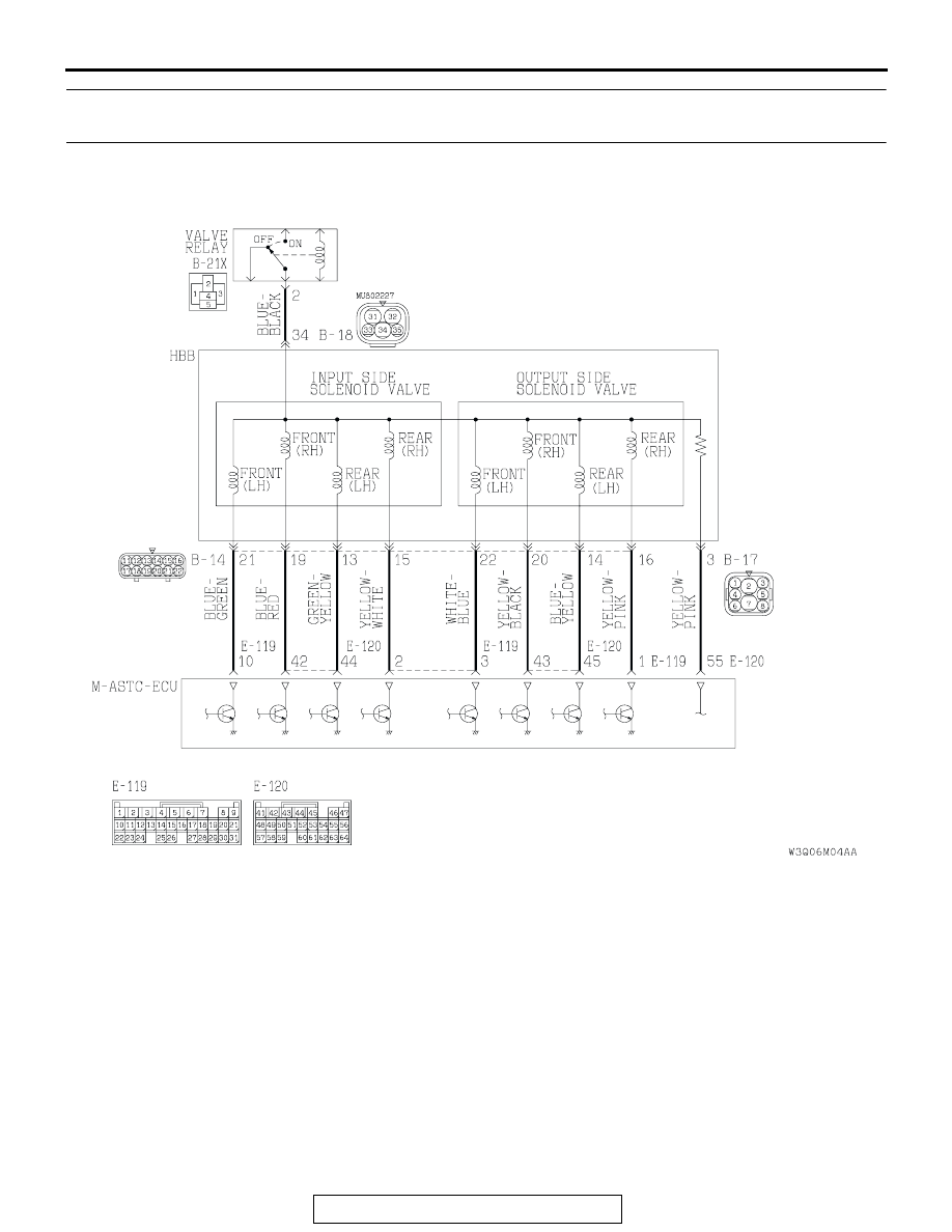
DTC 41, 42, 43, 44 : Control Solenoid Valve
DTC 45, 46: Select Solenoid Valve

AC204647AB

Control Solenoid Valve Circuit

ANTI-LOCK BRAKING SYSTEM (ABS) DIAGNOSIS

TSB Revision

ANTI-LOCK BRAKING SYSTEM (ABS)

35B-44

AC204648AB

Select Solenoid Valve Circuit

AC204702AB

B-17(GR)

CONNECTORS: B-14, B-17, B-18

B-18(B)

B-14(B)

AC204674

AB

B-21X (VALVE RELAY)

CONNECTOR: B-21X

ANTI-LOCK BRAKING SYSTEM (ABS) DIAGNOSIS

TSB Revision

ANTI-LOCK BRAKING SYSTEM (ABS)

35B-45

.

CIRCUIT OPERATION
As the ignition switch is turned ON, power is supplied 
to each solenoid valve via the valve relay. M-ASTC-
ECU, by turning ON the transistor, grounds the circuit 
and turns the solenoid valve ON.

.

ABS DTC SET CONDITIONS
The M-ASTC-ECU constantly monitors the solenoid 
valve drive circuits. These codes are output if the M-
ASTC-ECU judges that there is an open circuit or 
short-circuit in a solenoid coil or harness because the 
solenoid valve is on but no current flows to the sole-
noid valve, or if current continues flowing to the sole-
noid valve even though the solenoid valve is off.

.

TROUBLESHOOTING HINTS

• Damaged wiring harness or connector

• Malfunction of the M-ASTC-ECU

• Malfunction of the hydraulic brake booster (HBB)

.

AC203901AD

CONNECTORS: E-119, E-120

E-119

E-120

ANTI-LOCK BRAKING SYSTEM (ABS) DIAGNOSIS

TSB Revision

ANTI-LOCK BRAKING SYSTEM (ABS)

35B-46

DIAGNOSIS

Required Special Tool:

• MB991223: Harness Set

STEP 1. Check the solenoid valve circuit at M-ASTC-ECU 
connector E-119 and E-120 by backprobing.
(1) Do not disconnect connector E-119 and E-120.
(2) Turn the ignition switch to the "ON" position.
(3) Measure voltage between the following terminals. It should 

be approximately 12 volts (battery positive voltage).

When DTC 41 is set:

• M-ASTC-ECU connector E-120 terminal 43 and ground

• M-ASTC-ECU connector E-120 terminal 42 and ground

AC203901

AC204627AI

E-120

CONNECTOR: E-120

E-120

HARNESS CONNECTOR:
HARNESS SIDE


Content   ..  1041  1042  1043  1044   ..