Mitsubishi Montero (2002-2004). Manual - part 1037


  Index      Mitsubishi     Mitsubishi Montero - service repair manual 2002-2004 year


Search            


Content   ..  1035  1036  1037  1038   ..


Mitsubishi Montero (2002-2004). Manual - part 1037


ANTI-LOCK BRAKING SYSTEM (ABS) DIAGNOSIS

TSB Revision

ANTI-LOCK BRAKING SYSTEM (ABS)

35B-19

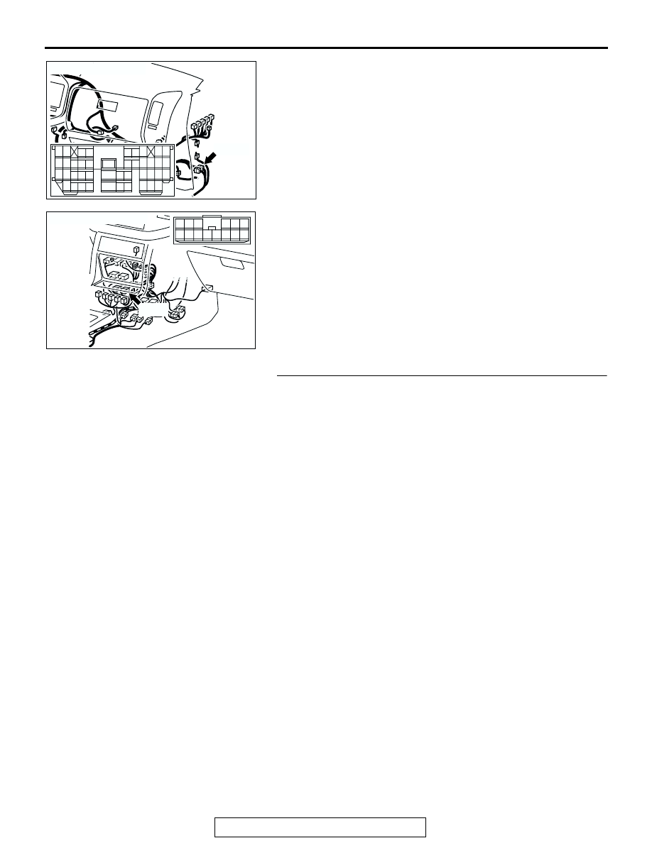
NOTE: After inspecting M-ASTC-ECU connector E-120, inter-
mediate connector D-111, E-110 and ABS sensor <rear: RH> 
connector G-14, inspect the wire. If M-ASTC-ECU connector E-
120, intermediate connector E-110, D-111 and ABS sensor 
<rear: RH> connector G-14 are damaged, repair or replace 
them. Refer to GROUP 00E, Harness Connector Inspection 

P.00E-2

. Then go to Step 9.

Q: Is the harness wire between M-ASTC-ECU connector E-

120 terminal 60 and ABS sensor <rear: RH> connector 
G-14 terminal 2 or M-ASTC-ECU connector E-120 
terminal 61 and ABS sensor <rear: RH> connector G-14 
terminal 1 damaged?
YES : 
Repair it and then go to Step 9.
NO :  Go to Step 9.

STEP 9. Recheck for diagnostic trouble code.
Q: Do the DTCs 11, 12, 13 or 14 reset?

YES : Go to Step 1.
NO :  The procedure is complete.

AC204384

CONNECTOR: D-111

D-111

AC

9

21

33

35

24

12

3 4

7

8

5 6

39

28

41

30

18

4243

31

1920

32

40

29

1617

38

27

15

37

36

26

14

13

25

2

1

34

23

11

10

22

AC204385

CONNECTOR: E-110

AD

E-110

6

1

7

2

9

8

10

3

5

12

11

4

1314

ANTI-LOCK BRAKING SYSTEM (ABS) DIAGNOSIS

TSB Revision

ANTI-LOCK BRAKING SYSTEM (ABS)

35B-20

DTC 21, 22, 23, 24: ABS Sensor

AC204644AB

ABS Sensor Circuit

AC000709AF

CONNECTOR: A-03

AC000710

CONNECTOR: A-24

AJ

ANTI-LOCK BRAKING SYSTEM (ABS) DIAGNOSIS

TSB Revision

ANTI-LOCK BRAKING SYSTEM (ABS)

35B-21

.

CIRCUIT OPERATION

• A toothed ABS rotor generates a voltage pulse as 

it moves across the pickup field of each ABS sen-
sor.

• The amount of voltage generated at each wheel 

is determined by the clearance between the ABS 
rotor teeth and the ABS sensor, and by the speed 
of rotation.

• The ABS sensors transmit the frequency of the 

voltage pulses and the amount of voltage gener-
ated by each pulse to the Mitsubishi active skid 
and traction control system-electronic control unit 
(M-ASTC-ECU).

• The ABS hydraulic unit modulates the amount of 

braking force individually applied to each wheel 
cylinder.

.

ABS DTC SET CONDITIONS
DTCs 21, 22, 23, 24 are output in the following 
cases:

• Open circuit is not found but no input is received 

by one or more of the four ABS sensors at 10 km/
h (6 mph) or more.

• Sensor output drops due to a malfunctioning sen-

sor or warped ABS rotor.

.

TROUBLESHOOTING HINTS
The most likely causes for these DTCs to set are:

• Malfunction of the ABS sensor

• Damaged wiring harness and connector

• Malfunction of the M-ASTC-ECU

• Malfunction of the ABS rotor

• Malfunction of the wheel bearing

• Excessive clearance between the sensor and 

ABS rotor

.

AC000711

CONNECTOR: A-37

AF

ACX02283

CONNECTOR: D-111

AD

ACX01852

E-110

CONNECTORS: E-105, E-110

AM

E-105

ACX02289AK

CONNECTOR: F-11

ACX02290

CONNECTORS: G-14, G-21

AE

G-14

G-21

ANTI-LOCK BRAKING SYSTEM (ABS) DIAGNOSIS

TSB Revision

ANTI-LOCK BRAKING SYSTEM (ABS)

35B-22

DIAGNOSIS

Required Special Tools:

• MB991223: Harness Set

• MB991502: Scan tool (MUT-II)

STEP 1. Using scan tool MB991502, check data list item 11, 
12, 13, 14: ABS sensor.

CAUTION

To prevent damage to scan tool MB991502, always turn the 
ignition switch to the "LOCK" (OFF) position before con-
necting or disconnecting scan tool MB991502.
(1) Connect scan tool MB991502 to the data link connector.
(2) Start the engine.
(3) Set scan tool MB991502 to data reading mode for item 11, 

12, 13, 14, ABS sensor.

• With the engine running, reading on the speedometer 

nearly matches the indication on scan tool MB991502.

Q: Is the ABS sensor input normal?

YES : This malfunction is intermittent. Refer to GROUP 00, 

How to Use Troubleshooting/Inspection Service 
Points 

− How to Cope With Intermittent Malfunction 

P.00-6

NO :  Go to Step 2.

STEP 2. Check the ABS sensor installation.
Q: Is the ABS sensor bolted securely in place at the front 

knuckle or the rear knuckle?
YES : 
Go to Step 3.
NO :  Install it properly. Refer to 

P.35B-124

. Then go to Step 

11.

ACX01539AE

MB991502

16-PIN

ACX01221

ABS SENSOR <FRONT>

AD

ACX01227AD

ABS SENSOR <REAR>


Content   ..  1035  1036  1037  1038   ..