Mitsubishi Montero (2002-2004). Manual - part 1029


  Index      Mitsubishi     Mitsubishi Montero - service repair manual 2002-2004 year


Search            


Content   ..  1027  1028  1029  1030   ..


Mitsubishi Montero (2002-2004). Manual - part 1029


FRONT DISC BRAKE ASSEMBLY

TSB Revision

BASIC BRAKE SYSTEM

35A-141

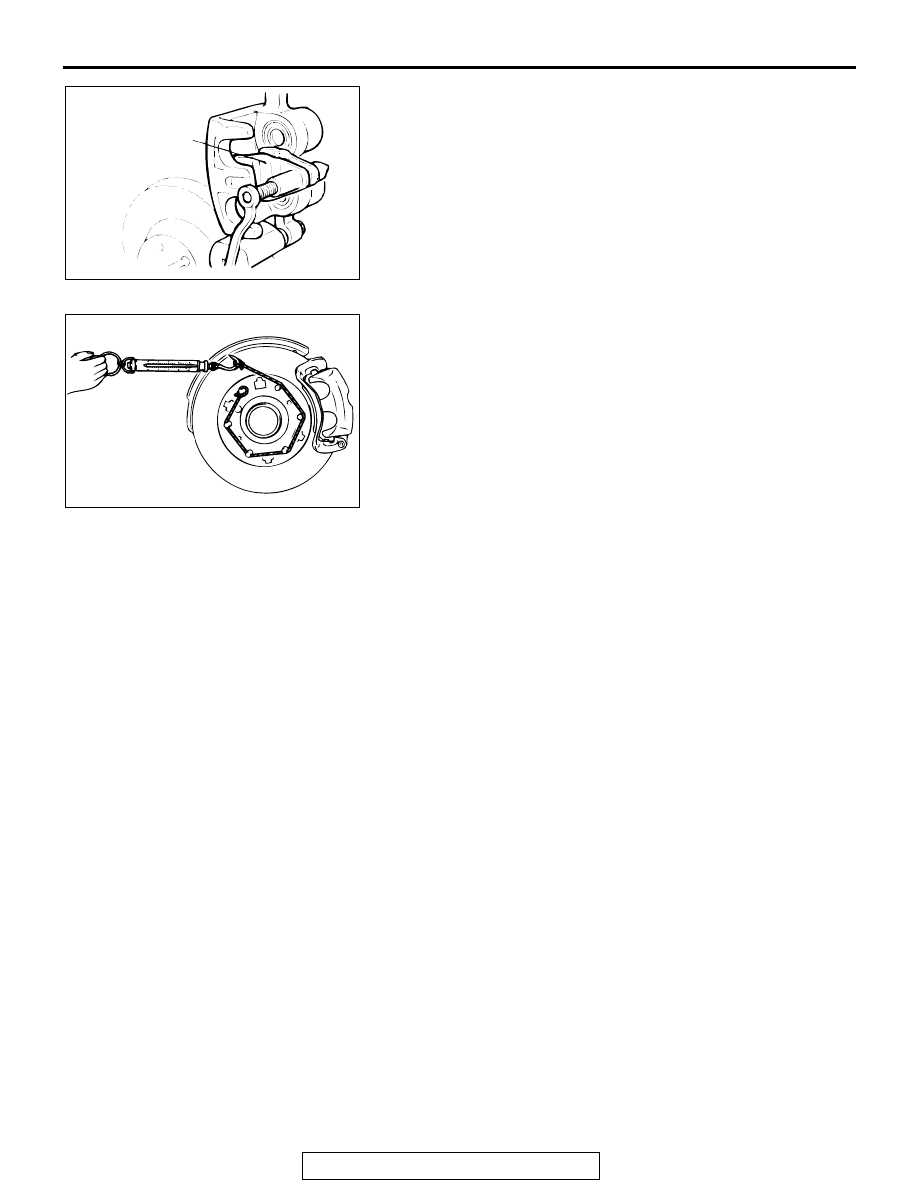
3. Clean the piston, and insert into cylinder with special tool 

MB990520.

4. Be careful that the piston boot does not become caught 

when lowering the caliper assembly and installing the guide 
pin.

5. Check the brake drag force as follows:

(1) Start the engine and hold the brake pedal down for five 

seconds. [Pedal depression force: approximately 196 N 
(44 pound)]

(2) Stop the engine.
(3) Turn the brake disc forward 10 times.
(4) Use a spring scale to measure the hub torque with pads 

installed in the same direction as earlier.

(5) Calculate the drag force of the disc brake [difference 

between hub torque with pads installed and hub torque 
with pads removed].

Standard value: 55 N (12 pound)

6. If the brake drag force exceeds the standard value, 

disassemble and clean the piston. Check for corrosion or 
worn piston seal, and check the sliding condition of the lock 
pin and guide pin.

INSPECTION

M1351006100181

Brake Disc Check

• Disc wear (Refer to 

P.35A-130

.)

• Disc run-out (Refer to 

P.35A-130

.)

ACX00684AB

MB990520

ACX00685

FRONT DISC BRAKE ASSEMBLY

TSB Revision

BASIC BRAKE SYSTEM

35A-142

DISASSEMBLY AND ASSEMBLY

M1351006200285

ACX00686AB

89 ± 4 N

m

66 ± 3 ft-lb

89 ± 4 N

m

66 ± 3 ft-lb

7.4 ± 1.4 N

m

65 ± 13 in-lb

2

2

1

1

9

9

13

13

13

13

13

13

10

11

12

12

4

4

4

8

8

8

7

7

6

6

6

5

5

5

3

3

CLIP KIT

10

11

BRAKE CALIPER KIT

PAD SET

SHIM KIT

SEAL AND BOOT KIT

N

N

N

N

DISASSEMBLY STEPS

1. GUIDE PIN LOCK BOLT
2. GUIDE PIN
3. CALIPER SUPPORT, PAD, CLIP AND 

SHIM ASSEMBLY

4. BOOT
5. BUSHING

<<A>>

6. PISTON BOOT

<<A>>

7. PISTON

<<B>>

8. PISTON SEAL
9. CALIPER BODY
10. PAD AND WEAR INDICATOR 

ASSEMBLY

11. PAD ASSEMBLY
12. SHIM
13. CLIP

DISASSEMBLY STEPS (Continued)

FRONT DISC BRAKE ASSEMBLY

TSB Revision

BASIC BRAKE SYSTEM

35A-143

LUBRICATION POINTS

DISASSEMBLY SERVICE POINTS

CAUTION

When disassembling the front disc brakes, disassemble 
both sides (left and right wheels) as a set.

.

ACX00687AC

GREASE: REPAIR KIT GREASE

GREASE: REPAIR KIT GREASE

BRAKE FLUID: DOT3 OR DOT4

THE PISTON SEAL INSIDE THE
SEAL AND BOOT KIT IS COATED
WITH SPECIAL GREASE DO NOT 
WIPE THIS GREASE OFF.

GREASE: REPAIR KIT GREASE

PISTON
SEAL

CAUTION

FRONT DISC BRAKE ASSEMBLY

TSB Revision

BASIC BRAKE SYSTEM

35A-144

<<A>> PISTON BOOT/PISTON REMOVAL

CAUTION

• When removing the pistons, be sure to use the handle 

of a plastic hammer and adjust the height of the two 
pistons while pumping in air slowly so that the pistons 
protrude evenly.

• Do not remove one piston completely before trying to 

remove the other piston, because it will become impos-
sible to remove the second piston.

• Blow air little by little to remove the piston. The piston 

will rush out if a force of air is applied suddenly.

Blow compressed air slowly from the connecting portion of the 
brake hose to pull out the piston and the piston boots.

.

<<B>> PISTON SEAL REMOVAL

CAUTION

Do not use a flat-tipped screwdriver or similar tool to 
remove piston seal. These may damage the inner side of 
the cylinder.
1. Remove the piston seal with your finger tip.
2. Clean the piston surface and inner cylinder with alcohol 

brake fluid DOT 3 or DOT 4.

ACX00688

ACX00689


Content   ..  1027  1028  1029  1030   ..