Mitsubishi Montero (2002-2004). Manual - part 92
AUTO A/C DIAGNOSIS
TSB Revision
AUTOMATIC AIR CONDITIONING
55B-61
.
TECHNICAL DESCRIPTION (COMMENT)
If the blower fan and motor does not turn when the
blower switch is operated, the blower motor circuit
may be defective.
.
TROUBLESHOOTING HINTS
• Malfunction of the blower relay
• Malfunction of the heater blower controller unit
• Malfunction of the flexible flat cable
• Malfunction of the blower motor
• Malfunction of the automatic air-conditioning con-
trol panel
• Damaged harness wires or connectors
DIAGNOSIS
STEP 1. Using scan tool MB991502, check actuator test
item 01, item 02, item 03 and item 04: Blower motor.
Carry out the actuator test.
Item 01, 02, 03 and 04: Blower motor
Q: Do the check results show "Stop" (01 activated), "low
speed" (02 activated), "medium speed" (03 activated),
and "high speed" (04 activated)?
YES : Go to Step 25.
NO : Go to Step 2.
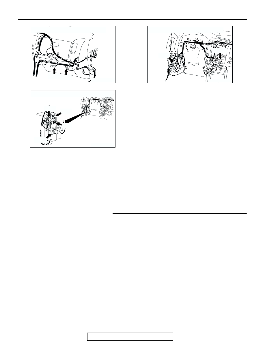
AC204171 BC
D-17 D-113
CONNECTORS : D-17, D-113
AC204170
CONNECTORS : D-23, D-28
DW
D-28
D-23(B)
AC204173
CONNECTORS : D-208, D-209, D-211, D-218
BH
D-208
D-218
D-209
D-211(B)