Mitsubishi Montero (2002-2004). Manual - part 51
REAR AIR CONDITIONING DIAGNOSIS
TSB Revision
HEATER, AIR CONDITIONING AND VENTILATION
55A-67
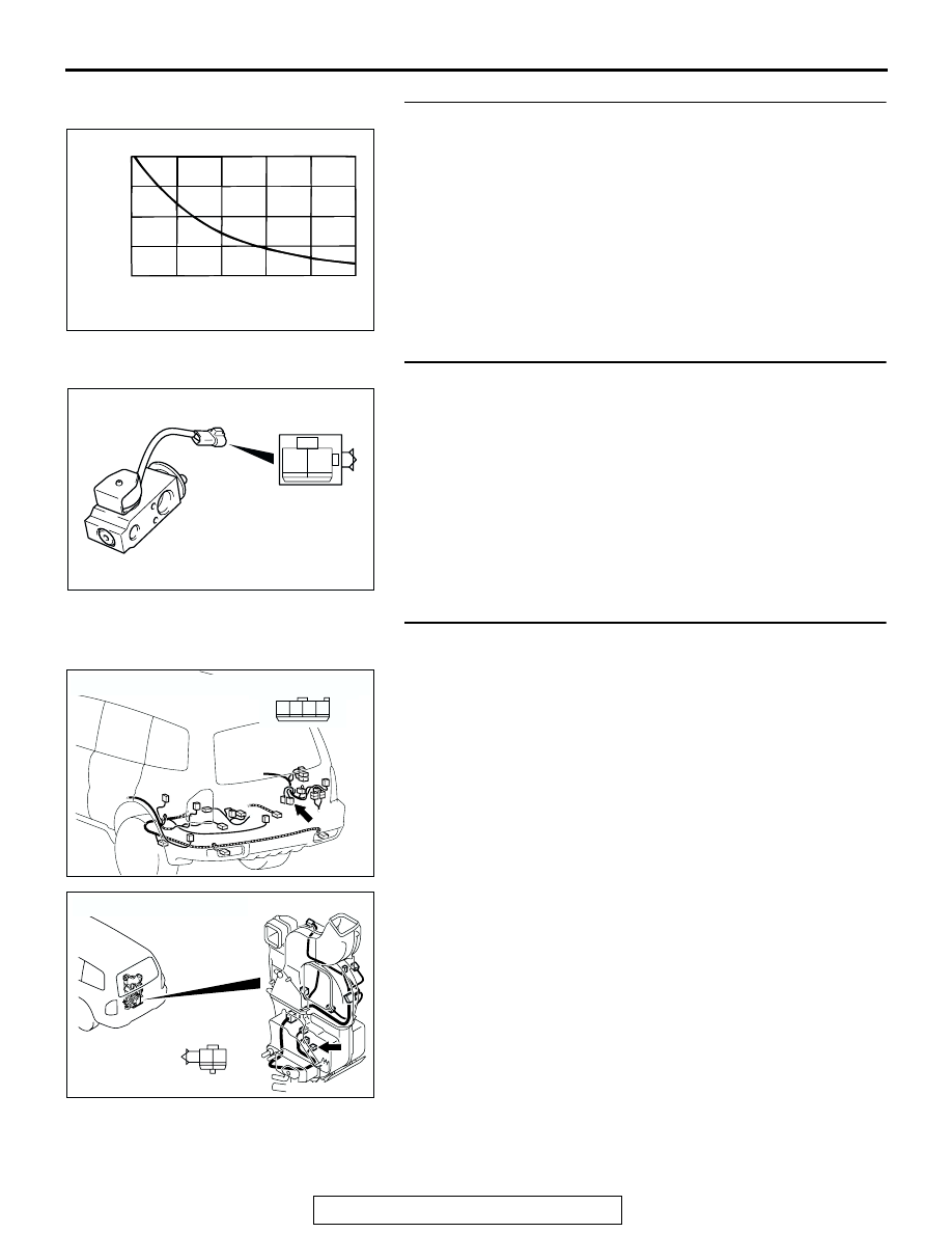
STEP 13. Check the air thermo sensor.
When the resistance between the sensor terminals is mea-
sured at two or more temperature conditions, the resistance
should satisfy the value shown in the illustration.
NOTE: The temperature condition at the check shall be within
the range shown in the characteristic diagram.
Q: Does air thermo sensor work normally?
YES : Go to Step 14.
NO : Replace the air thermo sensor.
STEP 14. Check the expansion valve (magnet valve).
The valve is in normal condition if the actuation sound is heard
from the magnet valve when battery voltage is applied to mag-
net valve terminal 2 and terminal 1 is grounded.
Q: Does expansion valve work normally?
YES : Go to Step 15.
NO : Replace the expansion valve (magnet valve).
STEP 15. Check rear A/C unit connector G-24 and
magnetic valve connector G-26-4 for damage.
Q: Is rear A/C unit connector G-24 and magnetic valve
connector G-26-4 in good condition?
YES : Go to Step 16.
NO : Repair or replace the connector. Refer to GROUP
00E, Harness Connector Inspection
that the rear air conditioning works normally.
AC001043
RESISTANCE k
Ω
8
6
4
2
0
-10
0
10
20
30
40
TEMPERATURE ˚C(˚F)
AB
(14)
(32)
(50)
(86)
(104)
(68)
1 2
AC102582
AC204179
CONNECTOR : G-24
AQ
HARNESS SIDE
1
2
3
4
AC204698
CONNECTOR : G-26-4
AM
HARNESS SIDE
2 1