Mitsubishi Montero (2002-2004). Manual - part 38


  Index      Mitsubishi     Mitsubishi Montero - service repair manual 2002-2004 year


Search            


Content   ..  36  37  38  39   ..


Mitsubishi Montero (2002-2004). Manual - part 38


MANUAL A/C DIAGNOSIS

TSB Revision

HEATER, AIR CONDITIONING AND VENTILATION

55A-15

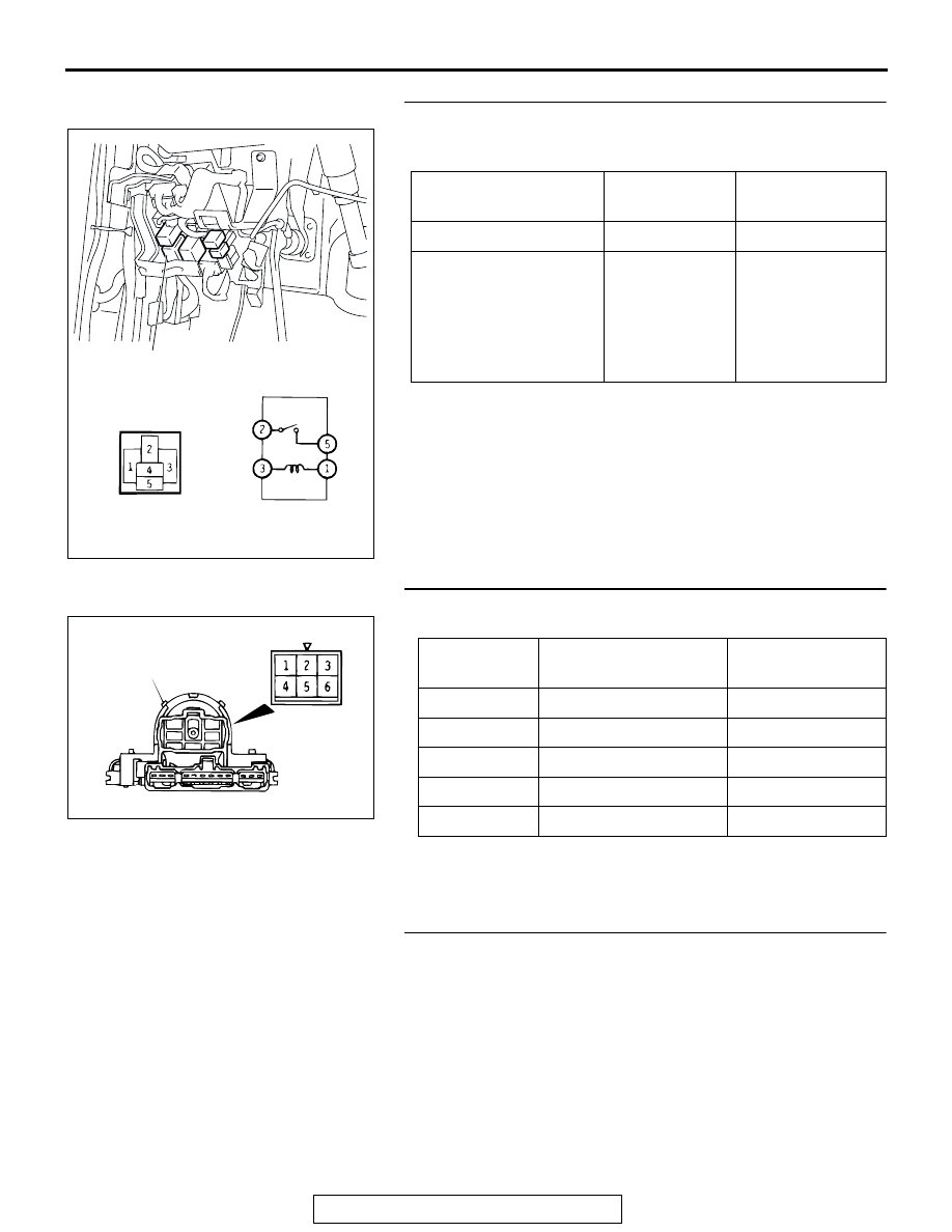
STEP 2. Check the front blower relay continuity.
Follow the table below to check the front blower relay for conti-
nuity.

Q: Is there continuity at the front blower relay?

YES : Go to Step 3.
NO :  Replace the front blower relay. Then go to Step 4.

STEP 3. Check the blower switch continuity.
Follow the table below to check the blower switch for continuity.

Q: Is there continuity at the blower switch?

YES : Go to Step 4.
NO :  Replace the blower switch. Then go to Step 4.

STEP 4. Retest the system.
Q: Does the blower motor stop operating?

YES : The procedure complete. (If no malfunctions are not 

found in all steps, an intermittent malfunction is 
suspected. Refer to GROUP 00, How to Use 
Troubleshooting/Inspection Service Points 

− How to 

Cope with Intermittent Malfunction 

P.00-6

.)

NO :  Go to Step 1.

BATTERY VOLTAGE

TESTER 
CONNECTION 

SPECIFIED 
CONDITION

Not applied

− 5

Open circuit

• Connect terminal 3 

to the positive 
battery terminal

• Connect terminal 1 

to the negative 
battery terminal

− 5

Less than 2 ohms

AC204714AB

FRONT BLOWER RELAY

SWITCH 
POSITION

TESTER 
CONNECTION 

SPECIFIED 
CONDITION

0 (OFF)

− 3, 3 − 4, 3 − 5, 3 − 6 Open circuit

1 (LO)

− 5

Less than 2 ohms

2 (ML)

− 3

Less than 2 ohms

3 (MH)

− 6

Less than 2 ohms

4 (HI)

− 4

Less than 2 ohms

AC001371

BLOWER SWITCH
ASSEMBLY

AB

MANUAL A/C DIAGNOSIS

TSB Revision

HEATER, AIR CONDITIONING AND VENTILATION

55A-16

INSPECTION PROCEDURE 6: When the A/C is Operating Condenser Fan does not turn.

DIAGNOSIS

STEP 1. Check the condenser fan relay continuity.
Follow the table below to check the condenser fan relay for 
continuity.

Q: Is there continuity at the fan control relay?

YES : Go to Step 2.
NO :  Replace the condenser fan relay. Then go to Step 4.

STEP 2. Check the condenser fan motor operation.
Follow the table below to check the condenser fan relay for 
continuity.

Q: Is the condenser fan motor operating correctly?

YES : Go to Step 3.
NO :  Replace the condenser fan motor. Then go to Step 3.

STEP 3. Measure the PCM terminal voltage.
Refer to GROUP 13A, Check at PCM terminal

P.13Ab-43

.

Q: Is the PCM voltage correct?

YES : Go to Step 4.
NO :  Replace the PCM. Then go to Step 4.

BATTERY VOLTAGE

TESTER 
CONNECTION 

SPECIFIED 
CONDITION

Not applied

− 5

Open circuit

• Connect terminal 3 

to the positive 
battery terminal

• Connect terminal 1 

to the negative 
battery terminal

− 5

Less than 2 ohms

AC204715

3

1

4

5

AD

CONDENSER 
FAN RELAY

BATTERY

CONNECT 
POSITIVE 
BATTERY 
TERMINAL TO

CONNECT 
NEGATIVE 
BATTERY 
TERMINAL TO

MOTOR OPERATION

1

2

Rotates

ACX00845 AC

MANUAL A/C DIAGNOSIS

TSB Revision

HEATER, AIR CONDITIONING AND VENTILATION

55A-17

STEP 4. Retest the system.
NOTE: The condenser fan might not operate when there is an 
air conditioning low load from the air conditioning condenser 
control, so remove the negative battery terminal and then 
check the symptoms after 5 minutes since initial start control 
after reconnection.
Q: Is the condenser fan operating correctly?

YES : The procedure complete. (If no malfunctions are not 

found in all steps, an intermittent malfunction is 
suspected. Refer to GROUP 00, How to Use 
Troubleshooting/Inspection Service Points 

− How to 

Cope with Intermittent Malfunction 

P.00-6

.)

NO :  Go to Step 1.

INSPECTION PROCEDURE 7: Inside/Outside Air changeover is not possible.

DIAGNOSIS

STEP 1. Check the outside/inside air selection damper 
control motor operation.

CAUTION

Disconnect the battery negative terminal when the damper 
is in the inside/outside air position.
Check the outside/inside air selection damper control motor by 
the following procedures.

Q: Is the outside/inside air selection damper control motor 

operating correctly?
YES : 
Go to Step 2.
NO :  Replace the outside/inside air selection damper 

control motor. Then go to Step 4.

LEVER POSITION BATTERY 

CONNECTION

LEVER 
OPERATION

At the inside air 
position

• Connect 

terminal 1 to the 
positive battery 
terminal

• Connect 

terminal 2 to the 
negative battery 
terminal

The lever moves 
from the inside air 
position to the 
outside air position

At the outside air 
position

• Connect 

terminal 1 to the 
positive battery 
terminal

• Connect 

terminal 3 to the 
negative battery 
terminal

The lever moves 
from the outside air 
position to the 
inside air position

2 3

1

AC001041AB

OUTSIDE 
AIR

INSIDE AIR

MANUAL A/C DIAGNOSIS

TSB Revision

HEATER, AIR CONDITIONING AND VENTILATION

55A-18

STEP 2. Check the outside/inside air selection switch 
continuity.
Follow the table below to check the inside/outside air 
changeover switch for continuity.

Q: Is there continuity at the outside/inside air selection 

switch?
YES : 
Go to Step 3.
NO :  Replace the outside/inside air selection switch. Then 

go to Step 4.

STEP 3. Measure the automatic compressor controller 
terminal voltage.
Refer to 

P.55A-18

.

Q: Is the automatic compressor controller terminal voltage 

correct?
YES : 
Go to Step 4.
NO :  Replace the automatic compressor controller. Then 

go to Step 4.

STEP 4. Retest the system.
Q: Do the outside/inside air selection damper control 

motor operate?
YES : 
The procedure complete. (If no malfunctions are not 

found in all steps, an intermittent malfunction is 
suspected. Refer to GROUP 00, How to Use 
Troubleshooting/Inspection Service Points 

− How to 

Cope with Intermittent Malfunction 

P.00-6

.)

NO :  Go to Step 1.

INSPECTION AT THE AUTOMATIC COMPRESSOR CONTROLLER TERMINAL

M1552010300323

SWITCH 
POSITION

TESTER 
CONNECTION 

SPECIFIED 
CONDITION

Inside air

− 5

Open circuit

Outside air

− 5

Less than 2 ohms

AC001370

OFF

ON

BLOWER
SWITCH
ASSEMBLY

AB

28

27

23 24

26

25

21 22

1

11

2

12

3

13

4

14

5

15

6

16

7

17

8

18

9

19

10

20

AC101882

TERMINAL 
NO.

INSPECTION ITEM

INSPECTION REQUIREMENT

NORMAL CONDITION

1

IG2 power supply

Ignition switch ON

Battery positive voltage

2

Input from air thermo 
sensor to controller

Ignition switch and A/C switch: OFF

0 V

Ignition switch and A/C switch: ON

− 5 V


Content   ..  36  37  38  39   ..