Mitsubishi Montero (1998+). Manual - part 179


  Index      Mitsubishi     Mitsubishi Montero - service repair manual 1998 year


Search            


Content   ..  177  178  179  180   ..


Mitsubishi Montero (1998+). Manual - part 179


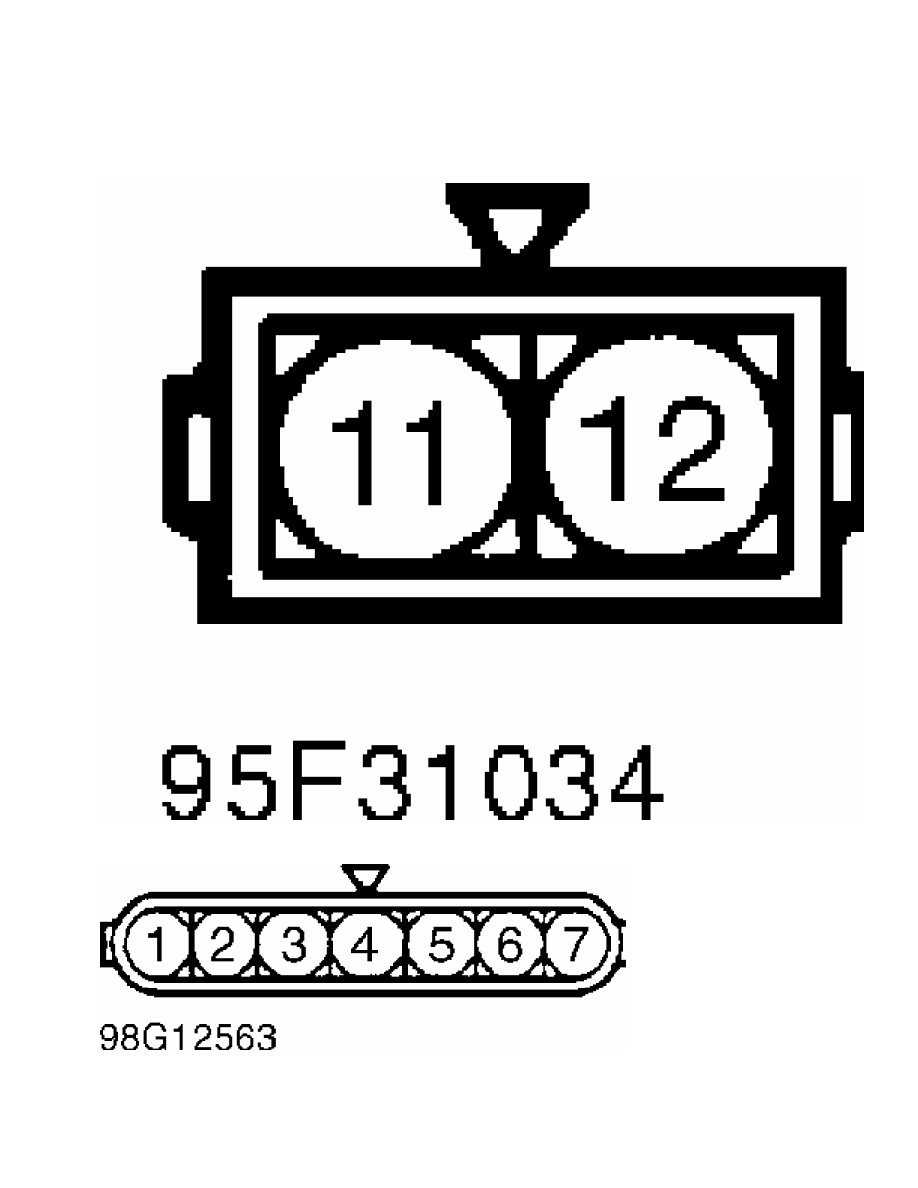
Fig. 10:  Ignition Coil Connectors Terminals (Except DIS - Galant)

Courtesy of Mitsubishi Motor Sales of America

Fig. 11:  Ignition Coil Connectors Terminals (Except DIS - Mirage

1.5L)

Courtesy of Mitsubishi Motor Sales of America

Fig. 12:  Ignition Coil Connectors Terminals (Except DIS - Montero

Sport 2.4L)

Courtesy of Mitsubishi Motor Sales of America

CAUTION: Power transistor test must be performed in less than 10

         seconds to prevent coil from burning or power transistor

         from breaking.

         Power Transistor (Diamante)

         1) Disconnect power transistor connector. Using a 1.5-volt

dry cell battery, connect negative end of 1.5-volt battery to terminal

No. 4 of power transistor and positive end to terminal No. 3. See

Fig. 13.

         2) Using an analog ohmmeter, check for continuity between

terminals No. 1 and 4 of power transistor. Continuity should exist.

With positive end of 1.5-volt battery disconnected, there should be no

continuity. Replace power transistor if it fails test.

         Power Transistor (Galant)

         1) Disconnect power transistor connector. Using a 1.5-volt

dry cell battery, connect negative end of 1.5-volt battery to terminal

No. 5 of power transistor and positive end to terminal No. 6. See

Fig. 14.

         2) Using an analog ohmmeter, check for continuity between

terminals No. 5 and 12 of power transistor. Continuity should exist.

With positive end of 1.5-volt battery disconnected, there should be no

continuity. Replace power transistor if it fails test.

         Power Transistor (Mirage)

         1) Disconnect power transistor (distributor) connector. Using

a 1.5-volt dry cell battery, connect negative end of 1.5-volt battery

to terminal No. 4 of power transistor and positive end to terminal No.

3. See Fig. 15.

         2) Using an analog ohmmeter, check for continuity between

terminals No. 2 and 4 of power transistor. Continuity should exist.

With positive end of 1.5-volt battery disconnected, there should be no

continuity. Replace power transistor if it fails test.

         Power Transistor (3000GT SOHC)

         1) Disconnect power transistor connector. Using a 1.5-volt

dry cell battery, connect negative end of 1.5-volt battery to terminal

No. 2 of power transistor and positive end to terminal No. 1. See

Fig. 15.

         2) Using an analog ohmmeter, check for continuity between

terminals No. 2 and 3 of power transistor. Continuity should exist.

With positive end of 1.5-volt battery disconnected, there should be no

continuity. Replace power transistor if it fails test.

Fig. 13:  Power Transistor Connectors (Except DIS - Diamante)

Courtesy of Mitsubishi Motor Sales of America

Fig. 14:  Power Transistor Connectors (Except DIS - Galant)

Courtesy of Mitsubishi Motor Sales of America

Fig. 15:  Power Transistor Connectors (Except DIS - Mirage & 3000GT

SOHC)

Courtesy of Mitsubishi Motor Sales of America

         IDLE SPEED & IGNITION TIMING

         Ensure idle speed and ignition timing are set to

specification. See IGNITION TIMING SPECIFICATIONS table. For

adjustment procedures, see D - ADJUSTMENTS article.

IGNITION TIMING SPECIFICATIONS (Degrees BTDC @ RPM) TABLE


Application           (1) Base            (2) (3) (4) Actual

1.5L  ...........  2-78@ 650-750  ............  10 @ 600-800

1.8L  ...........  2-8 @ 600-800  .............  5 @ 600-800

2.0L

  Non-Turbo  .........  (5)  ..........................  (5)

  Turbo  ........  2-8 @ 650-850  .............  8 @ 650-850

2.4L  ...........  2-8 @ 650-850  ............  10 @ 650-850

3.0L  ...........  2-8 @ 600-800  ............  15 @ 600-800

3.5L  ...........  2-8 @ 600-800  ............  15 @ 600-800

(1) - With ignition timing adjustment connector grounded or

      vacuum hose (farthest from distributor) disconnected.

(2) - With ignition timing adjustment connector ungrounded

      or vacuum hose (farthest from distributor) connected.

(3) - If vehicle altitude is more than 2300 feet above sea

      level, actual timing may be advanced (5 degrees).

(4) - Actual ignition timing is approximate and may

      fluctuate plus or minus 7 degrees.

(5) - Ignition timing is NOT adjustable.


         SUMMARY

         If no faults were found while performing BASIC DIAGNOSTIC

PROCEDURES, proceed to G - TESTS W/CODES article. If no hard codes are

found in self-diagnostics, proceed to H - TESTS W/O CODES article for

diagnosis by symptom (i.e., ROUGH IDLE, NO START, etc.) or

intermittent diagnostic procedures.


Content   ..  177  178  179  180   ..