Mitsubishi Montero (1998+). Manual - part 147


  Index      Mitsubishi     Mitsubishi Montero - service repair manual 1998 year


Search            


Content   ..  145  146  147  148   ..


Mitsubishi Montero (1998+). Manual - part 147


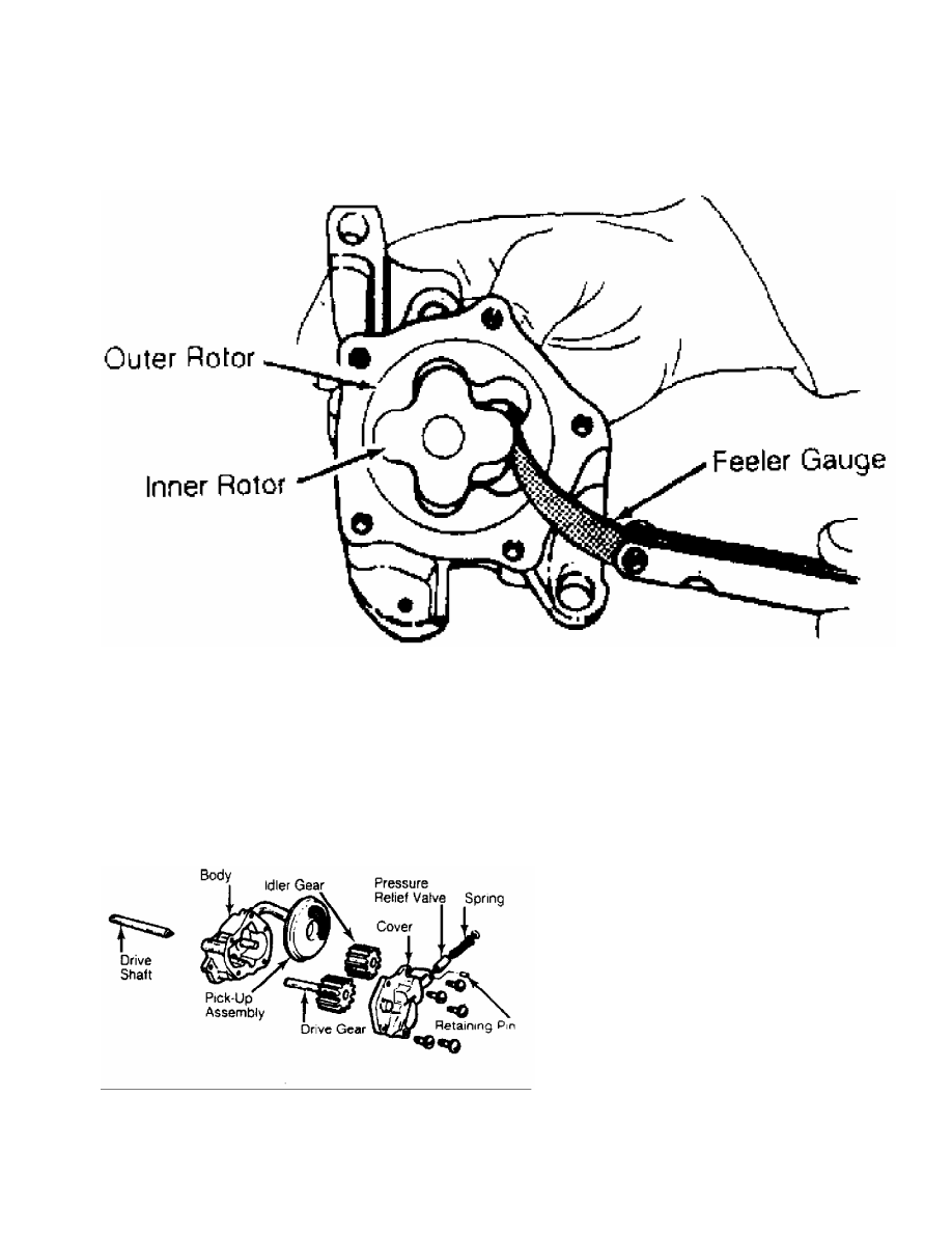
Fig. 31:  Measuring Rotor Clearance - Typical

This Graphic For General Information Only

         Install rotors in pump body. Position straightedge across

pump body. Using feeler gauge, measure clearance between rotors and

straightedge. Pump cover wear is measured using a straightedge and

feeler gauge. Replace pump if clearance exceeds specification.

         GEAR TYPE

         Oil pump gears must be marked for location prior to removal.

See Fig. 32. Remove gears from pump body. Inspect gears for pitting

or damage. Inspect cover for grooving or wear.

Fig. 32:  Typical Gear Type Oil Pump

This Graphic For General Information Only

         Measure gear diameter and length. Measure gear housing cavity

depth and diameter. See Fig. 33. Replace components if worn or

damaged.

         Pump cover wear is measured using a straightedge and feeler

gauge. Pump is to be replaced if warpage or wear exceeds

specifications or mating surface of pump cover is scratched or

grooved.

Fig. 33:  Measuring Oil Pump Gear Cavity - Typical

This Graphic For General Information Only

         BREAK-IN-PROCEDURE

         * PLEASE READ THIS FIRST *

NOTE:    Always refer to appropriate engine overhaul article in the

         ENGINES section for complete overhaul procedures and

         specifications for the vehicle being repaired.

         ENGINE PRE-OILING

         Engine pre-oiling should be done prior to operation to

prevent engine damage. A lightly oiled pump will cavitate unless oil

pump cavities are filled with engine oil or petroleum jelly.

         Engine pre-oiling can be done using pressure oiler (if

available). Connect pressure oiler to cylinder block oil passage

such as oil pressure sending unit. Operate pressure oiler long enough

to ensure correct amount of oil has filled crankcase. Check oil level

while pre-oiling.

         If pressure oiler is not available, disconnect ignition

system. Remove oil pressure sending unit and replace with oil pressure

test gauge. Using starter motor, rotate engine starter until gauge

shows normal oil pressure for several seconds. DO NOT crank engine

for more than 30 seconds to avoid starter motor damage.

         Ensure oil pressure has reached the most distant point from

the oil pump. Reinstall oil pressure sending unit. Reconnect ignition

system.

         INITIAL START-UP

         Start the engine and operate engine at low speed while

checking for coolant, fuel and oil leaks. Stop engine. Recheck coolant

and oil level. Adjust if necessary.

         CAMSHAFT

         Break-in procedure is required when a new or reground

camshaft has been installed. Operate and maintain engine speed between

1500-2500 RPM for approximately 30 minutes. Procedure may vary due to

manufacturers recommendations.

         PISTON RINGS

         Piston rings require a break-in procedure to ensure seating

of rings to cylinder walls. Serious damage may occur to rings if

correct procedures are not followed.

         Extremely high piston ring temperatures are produced obtained

during break-in process. If rings are exposed to excessively high RPM

or high cylinder pressures, ring damage can occur. Follow piston ring

manufacturer’s recommended break-in procedure.

         FINAL ADJUSTMENTS

         Check or adjust ignition timing and dwell (if applicable).

Adjust valves (if necessary). Adjust carburetion or injection idle

speed and mixture. Retighten cylinder heads (if required). If

cylinder head or block is aluminum, retighten bolts when engine is

cold. Follow the engine manufacturer’s recommended break-in procedure

and maintenance schedule for new engines.

NOTE:    Some manufacturer’s require that head bolts be retightened

         after specified amount of operation. This must be done to

         prevent head gasket failure.

* ENGINE SYSTEMS UNIFORM INSPECTION GUIDELINES * 

1998 Mitsubishi Montero

         GENERAL INFORMATION

         Engine Performance and Maintenance Motorist Assurance Program

         Standards For Automotive Repair

         All Makes and Models

         INTRODUCTION TO MOTORIST ASSURANCE PROGRAM (MAP)

         CONTENTS

         Motorist Assurance Program (MAP)

         OVERVIEW OF MOTORIST ASSURANCE PROGRAM

         OVERVIEW OF SERVICE REQUIREMENTS AND SUGGESTIONS

         Engine Assemblies

         CYLINDER HEAD ASSEMBLIES

         LONG BLOCK ASSEMBLIES

         SHORT BLOCK ASSEMBLIES

         Engine Components

         ACCELERATOR PEDAL POSITION SENSORS

         ACCESSORY BELTS

         ACCESSORY PULLEYS

         ACTUATORS

         AIR CONDITIONING CYCLING SWITCHES

         AIR CONDITIONING PRESSURE SENSORS

         AIR DUCTS AND TUBES

         AIR FILTER ELEMENTS

         AIR FILTER GASKETS

         AIR FILTER HOUSINGS AND GASKETS

         AIR FUEL RATIO SENSORS

         AIR INJECTION CONTROL SOLENOIDS

         AIR PLENUMS

         AIR PUMP BELTS

         AIR PUMPS (ELECTRIC-DRIVEN)

         AIR TUBES

         ASPIRATOR, CHECK AND DECEL VALVES

         BAFFLES

         BALLAST PRIMARY SUPPLY RESISTOR WIRES

         BALLAST RESISTORS AND PRIMARY SUPPLY RESISTOR WIRES

         BAROMETRIC PRESSURE SENSORS

         BATTERIES

         BATTERY CABLES, WIRES AND CONNECTORS

         BATTERY CONNECTORS

         BATTERY TRAYS AND HOLD DOWN HARDWARE

         BATTERY WIRES

         BELT-DRIVEN AIR PUMPS

         BELT IDLER ASSEMBLIES (ACCESSORY AND CAM BELTS)

         BELT TENSIONERS (ACCESSORY AND CAM BELTS)

         BOOST CONTROL MECHANISMS

         CAMSHAFT POSITION SENSORS

         CARBURETORS AND CHOKES

         CASTING CORE PLUGS AND EXPANSION PLUGS

         CHARGE AIR COOLERS "INTERCOOLERS" (CAC)

         CHECK VALVES

         CHOKES


Content   ..  145  146  147  148   ..