Mitsubishi Montero (1998+). Manual - part 96


  Index      Mitsubishi     Mitsubishi Montero - service repair manual 1998 year


Search            


Content   ..  94  95  96  97   ..


Mitsubishi Montero (1998+). Manual - part 96


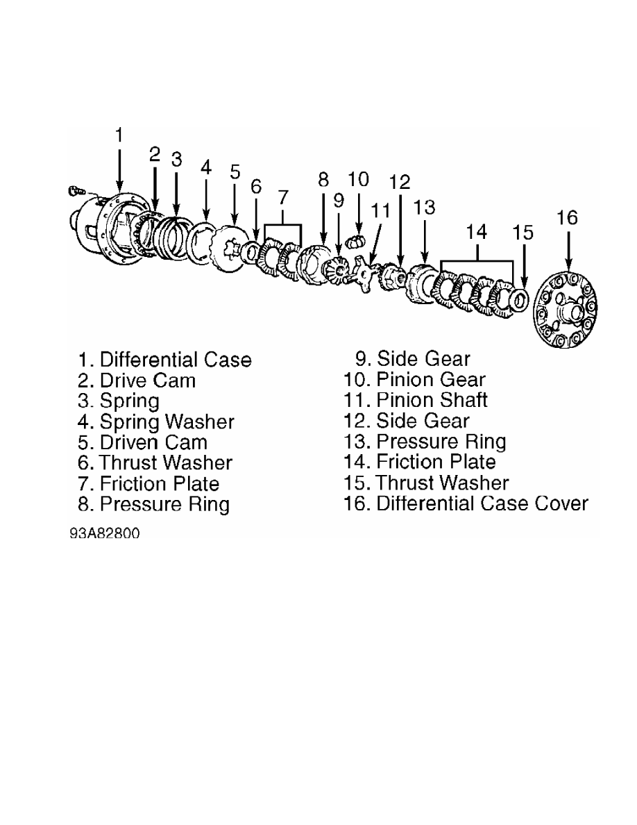
Fig. 12:  Exploded View Of Locking Differential

Courtesy of Mitsubishi Motor Sales of America.

         Reassembly

         1) Arrange friction plates and discs of each side of

differential. Measure each assembly thickness. Assembled discs and

plates should not exceed a difference of .002" (.05 mm). Replace discs

or plates as needed.

         2) Assemble one spring plate and one spring disc on each

side. Measure assembly thickness. Assemble disc and plates to obtain

minimum difference in thickness between each assembly.

         3) Assemble clutch assemblies, pressure rings, pinion gears,

side gears and pinion shaft. Measure overall width of assembly plus

spring plates and spring discs (dimension "C"). See  Fig. 13.

         4) Determine depth of differential case (dimension "D"). On

2.4L, dimension "D" = "E" + "F" - "G"; on 3.0L, dimension "D" = "E" +

"H"

         See Fig. 14. Subtract "C" from "D" to determine spring plate-

to-case clearance. Adjust spring disc thickness to obtain proper

spring plate-to-case clearance. Correct clearance is .0024-.0079" (.

060-.200 mm).

Fig. 13:  Measuring Clutch Assembly Width

Courtesy of Mitsubishi Motor Sales of America.

Fig. 14:  Measuring Limited Slip Case Depth

Courtesy of Mitsubishi Motor Sales of America.

         5) Remove spring plates, spring discs, friction plates and

friction disc from pressure rings. Mark components for location.

Install thrust washers on each end of pressure rings. See  Fig. 15.

         6) Measure clearance from end of thrust washer to rear face

of pressure ring. Clearance should be .002" (.05 mm) or less. If

clearance is not as specified, select proper thickness thrust washers

to obtain correct clearance.

         7) Once correct thrust washers are determined, install thrust

washers on pressure rings. Squeeze pressure rings together, and

measure width (dimension "H") from end of thrust washer to remaining

thrust washer.

         8) Determine distance between thrust washer surfaces when

differential case is assembled (dimension "I"). Dimension "I" = "J" +

"K" + "L". Dimension "J" is the same as dimension "D" in step 4).

Fig. 15:  Measuring Thrust Washer Clearance

Courtesy of Mitsubishi Motor Sales of America.

         9) Subtract "H" from "I". This is the clearance between

thrust washer and differential case. Correct clearance is .002-.008"

(.05-.20 mm). If clearance is not within specification, change thrust

washer to obtain correct clearance.

         10) Apply gear oil and friction modifier to all components.

Install components in differential case. Ensure assembly order and

direction of clutch components are correct. See  Fig. 16.

Fig. 16:  Limited Slip Differential Assembly

Courtesy of Mitsubishi Motor Sales of America.

         11) Install differential case cover with reference marks

aligned. Tighten screws to specification in several steps. See

TORQUE SPECIFICATIONS. Ensure cases contact each other completely when

fully assembled. Check for incorrect clutch assembly if gap exists.

         12) Using Clutch Plate Preload Tool (MB990988), Shaft

(MB990989) and torque wrench, measure starting torque. See  Fig. 17.

Rotate unit slightly before measuring starting torque.


Content   ..  94  95  96  97   ..