Mitsubishi Montero (1991+). Manual - part 164


  Index      Mitsubishi     Mitsubishi Montero - service repair manual 1991 year


Search            


Content   ..  162  163  164  165   ..


Mitsubishi Montero (1991+). Manual - part 164


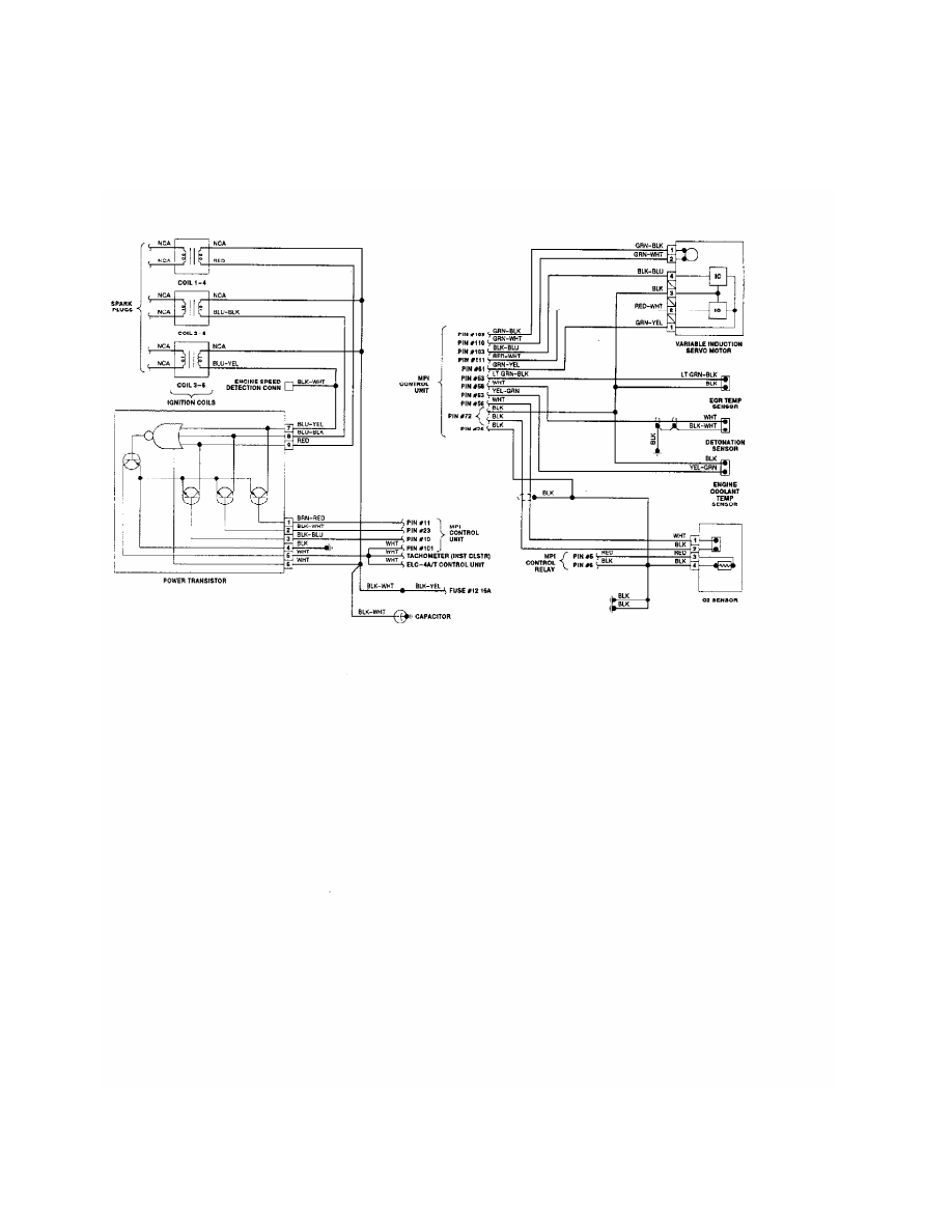
Fig. 15:  Wiring Diagram (Stealth & 3000GT 3.0L - DOHC - 2 of 2)

Fig. 16:  Wiring Diagram (Stealth & 3000GT 3.0L - Turbo - 1 of 2)

Fig. 17:  Wiring Diagram (Stealth & 3000GT 3.0L - Turbo - 2 of 2)

LOCKING HUBS 


1991 Mitsubishi Montero

         1991 DRIVE AXLES

         Locking Hubs

         Mitsubishi: Montero, Pickup

         DESCRIPTION

         Automatic hubs are engaged by rotational force of axle shaft

when 4WD is selected at transfer case. Automatic hubs disengage when

2WD is selected or vehicle is driven in Reverse. Cams, brakes and

springs are used to lock or unlock automatic hubs.

         Engagement is accomplished through gears and spring actions

within hub. When hub is locked, hub brake engages inner hub, which is

connected to axle shaft by inner splines of hub. Hub brake is

connected to hub body by outer splines.

         REMOVAL

         1) Hub must be unlocked. To unlock hub, place transfer case

lever in 2H position and move vehicle in Reverse approximately 4-6

feet.

         2) Remove cover from locking hub. If hub cover cannot be

loosened by hand, wrap shop towel around cover and use an oil filter

wrench to loosen cover.

         3) Raise and support vehicle. Remove wheel assembly. Using

snap ring pliers, remove snap ring and shim from end of axle. Remove

locking hub retaining bolts. Remove locking hub.

         INSTALLATION

         1) To install, reverse removal procedure. Apply sealant to

contact areas between locking hub assembly and hub/rotor assembly.

Ensure sealant is NOT applied on outer areas of hub/rotor assembly

toward brake contact areas.

         2) Align locking hub assembly key area with steering knuckle

key way area. Loosely install locking hub assembly on hub/rotor

assembly. Ensure locking hub assembly fully contacts hub/rotor

assembly.

         3) Install locking hub retaining bolts. Tighten bolts to 36-

43 ft. lbs. (49-58 N.m). Using spring scale attached to wheel stud,

measure turning resistance required to rotate hub/rotor assembly.

         4) Turning resistance should NOT exceed 3.1 lbs. (1.4 kg). If

turning resistance exceeds specification, check for incorrect

installation of locking hub assembly or components.

         5) Install shim and snap ring on drive axle. Rotate drive

axle until maximum end play is obtained. Using a dial indicator, check

drive axle end play.

         6) Drive axle end play should be .008-.020" (.20-.51 mm). If

axle end play is NOT within specification, adjust end play by changing

axle shaft shim. Install hub cover. Tighten hub cover 13-25 ft. lbs.

(18-34 N.m).

         OVERHAUL

         DISASSEMBLY


Content   ..  162  163  164  165   ..