Mitsubishi Montero (1991+). Manual - part 62


  Index      Mitsubishi     Mitsubishi Montero - service repair manual 1991 year


Search            


Content   ..  60  61  62  63   ..


Mitsubishi Montero (1991+). Manual - part 62


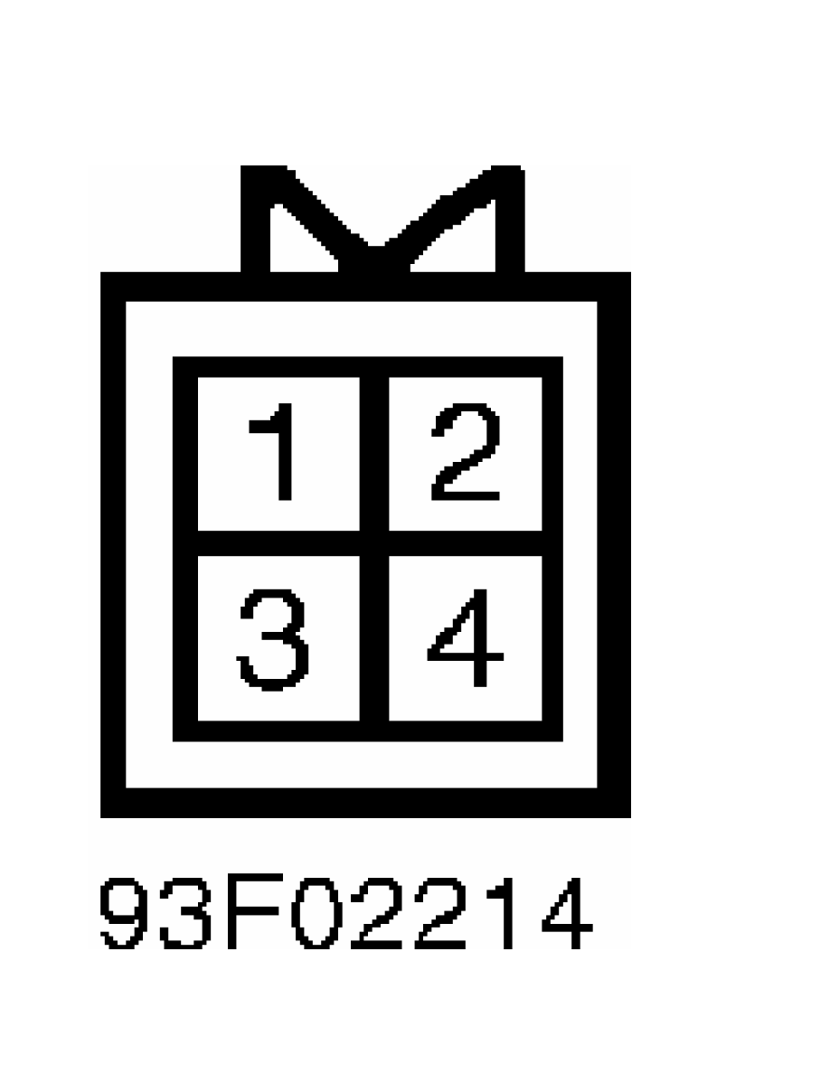
Fig. 25:  1992 Vacuum Pump Connector

Courtesy of Mitsubishi Motor Co.

Fig. 26:  1992 Instrument Cluster Connector

Courtesy of Mitsubishi Motor Co.

Fig. 27:  1992 Overdrive Switch Connector

Courtesy of Mitsubishi Motor Co.

Fig. 28:  1992 Inhibitor Switch Connector

Courtesy of Mitsubishi Motor Co.

Fig. 29:  1992 Throttle Position Sensor & Idle Switch Connector

Courtesy of Mitsubishi Motor Co.

         CRUISE CONTROL SWITCH TESTS

         Main, Set & Resume Switches (1991)

         1) Disconnect 6-pin cruise control switch connector. See

Figs. 17-21. With main switch in ON position, continuity should be

present between terminals No. 3 and 6 of cruise control switch

connector. With set switch in ON position, continuity should be

present between terminals No. 1 and 2.

         2) With resume switch in On position, continuity should be

present between terminals No. 2 and 4, and 3 and 6. If continuity is

not present, replace cruise control switch.

         Set & Resume Switches (1992)

         1) Remove lower steering column cover. Disconnect 2-pin

switch connector. Operate and test switch. When cancel switch is

operated, continuity should be present between terminals No. 1 and 2.

Zero ohms resistance should be indicated.

         2) When resume switch is operated, 820 ohms resistance should

be present between terminals No. 1 and 2. When set switch is operated,

2700 ohms resistance should be present between terminals No. 1 and 2.

Replace cruise control switch if it does not test correctly.

         Main Switch (1992)

         1) In each switch position, continuity should be present

between terminals No. 2 and 7 for switch illumination. See  Figs. 22-

29. When switch is moved to Neutral position, continuity should be

present between terminals No. 1 and 4.

         2) When switch is moved to ON position, continuity should be

present between terminals No. 1, 4 and 5. Connect battery voltage to

terminal No. 5 and ground terminal No. 4.

         3) Battery voltage should then be present on terminal No. 1

when main switch is moved to On position. Replace switch if it does

not test correctly.

         BRAKELIGHT/STOPLIGHT SWITCH TEST

         Disconnect switch connector. When brake pedal is pressed,

continuity should be present between terminals No. 2 and 3. See

Figs. 22-29. When brake pedal is released, continuity should be

present between terminals No. 1 and 4. Replace switch if it does not

test correctly.

         IDLE SWITCH & THROTTLE POSITION SENSOR TESTS

         Throttle Position Sensor (1992)

         1) Disconnect sensor connector. Resistance between terminals

No. 1 and 4 should be 3500-6500 ohms. Use an analog ohmmeter to

measure resistance between terminals No. 1 and 3. See  Figs. 22-29.

         2) Slowly open throttle valve to wide open throttle.

Resistance should change smoothly as throttle is opened. Replace

throttle position sensor if it does not test correctly.

         Idle Switch (1992)

         1) Disconnect throttle position sensor connector. Continuity

should be present between terminals No. 1 and 2 with accelerator pedal

released. See Figs. 22-29. Continuity should not be present with

accelerator pedal pressed.

         2) If continuity is not present with accelerator released,

loosen throttle position sensor mounting screw. Turn throttle position

sensor completely clockwise. Recheck continuity. Replace throttle

position sensor if idle switch does not test correctly.

         INHIBITOR SWITCH TEST

         Disconnect switch connector. Shift transaxle into Neutral and

Park positions. On 1991 models, continuity should be present between

Black/Yellow wire terminals No. 3 and 4. On 1992 models, continuity

should be present between terminals No. 7 and 12. See  Figs. 22-29. On

all models, if continuity is not present, adjust inhibitor switch. If

switch is adjusted properly, replace switch.

         VACUUM PUMP TEST

         1992

         1) Remove vacuum pump connector. Resistance should be 50-60

ohms between terminal No. 1 and terminals No. 2 and 3. See  Figs. 22-

29. Ensure solenoid valve makes operating noise when battery voltage

is applied between terminal No. 1 and terminals No. 2 and 3.

         2) If solenoid valve does not make noise, replace vacuum pump

assembly. Apply battery voltage to terminals No. 1 and 4, motor should

operate. Replace vacuum pump if motor does not operate.


Content   ..  60  61  62  63   ..